


Appendix A - sDIO Module
104 Adept SmartController User’s Guide, Rev. E
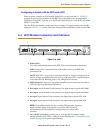
A.6 sDIO Digital I/O Signals
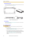
The sDIO module’s digital I/O signals are 64 optically isolated digital I/O channels (32
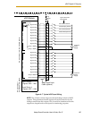
output and 32 input). They are wired to connectors X1 through X4, which are located on
the front of the sDIO (see Figure A-6 on page 103). The electrical specifications for the
inputs are similar to the XDIO inputs, but have a different wiring configuration. The sDIO
inputs cannot be used for REACTI programming, high-speed interrupts, or vision
triggers. See the V+ Language User’s Guide for information on digital I/O programming.
NOTE: The signals on the sDIO connectors can be superseded by another
sDIO that is installed and addressed as sDIO #1. To use two sDIO
modules, address the first as sDIO #1 and the second as sDIO #2.
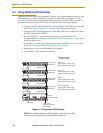
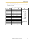
sDIO Inputs
The 32 input channels are arranged in four groups of eight. Each group is electrically
isolated from the other groups and is optically isolated from the sDIO module’s circuitry.
The eight inputs within each group share a common ground.
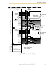
The inputs are accessed through the two female 26-pin D-sub input connectors on the
front of the sDIO. Each connector provides access to two input groups. Each group
requires ten pins, eight input signals, and two ground references. An input is activated by
providing a positive potential on its input pin relative to the ground pin of its group. This
type of input is considered sinking. That is current must flow into the input pin to turn it
on.
NOTE: The input current specifications are provided for reference. Voltage
sources are typically used to drive the inputs.
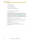
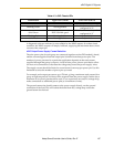
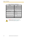
Table A-2. sDIO Input Specifications
Operational voltage range 0 to 24VDC
“Off” state voltage range 0 to 3VDC
“On” state voltage range 10 to 24VDC
Typical threshold voltage V
in
= 8VDC
Operational current range 0 to 6 mA
“Off” state current range 0 to.5 mA
“On” state current range 2 to 6 mA
Typical threshold current 2.5 mA
Impedance (V
in
/I
in
) 3.9 K Ω minimum
Current at V
in
= +24VDC I
in
≤ 6 mA
Turn on response time (hardware)
Software scan rate/response time
5 µsec maximum
16 ms scan cycle/
32 ms max response time
Turn off response time (hardware)
Software scan rate/response time
5 µsec maximum
16 ms scan cycle/
32 ms max response time