


Chapter 3 - SmartController Operation
54 Adept SmartController User’s Guide, Rev. E
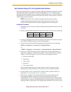
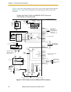
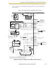
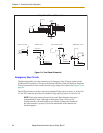
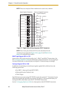
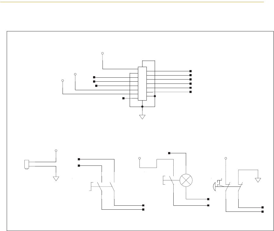
Figure 3-6. Front Panel Schematic
Emergency Stop Circuits
The SmartController provides connections for Emergency Stop (E-Stop) circuits on the
XUSR and XFP connectors. This gives the SmartController system the ability to duplicate
E-Stop functionality from a remote location using voltage-free contacts. See Figure 3-5 on
page 53.
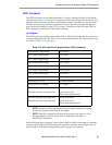
The XUSR connector provides external two-channel E-Stop input on pins 1 to 14 and 2 to
15. The XFP connector provides two-channel E-Stop input on pins 1 to 9 and 2 to 10.
NOTE: These pins must be shorted if not used. Both channels must open
independently if used. Although an Emergency Stop will occur, the
SmartController will malfunction if one channel is jumpered closed and
the other channel is opened. It will also malfunction if the channels are
shorted together.
ESTOPSRC
24VS
5VD
D
SYSPWRLT 7
6
5
4
2
3
1
17
16
8
10
9
11
12
13
14
15
XFP
15PDSUBM
MANUALSRC1
HIPWRREQ
MANUALRLY2
MANUALRLY1
HIPWRLT
ESTOPFP2
ESTOPFP1
HPLT5V
NC
MANUALSRC2
"MANUAL/AUTO""System Power LED"
MANUALSRC1
SW1
MANUALRLY2
MANUALRLY1
MANUALSRC2
24VS
"HIGH POWER ON/OFF"
SWL1
HIPWRREQ
HPLT5V
HIPWRLT
D
ESTOPSRC
"EMERGENCY STOP"
SW2
ESTOPFP2
ESTOPFP1
5VD
D
2PIN_MINI
SYSPWRLT
Adept Front Panel Schematic