


Installing and Maintaining the Versalar Switch Router 15000
3-16
308684-B Rev 00
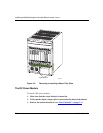
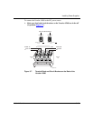
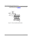
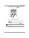
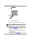
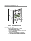
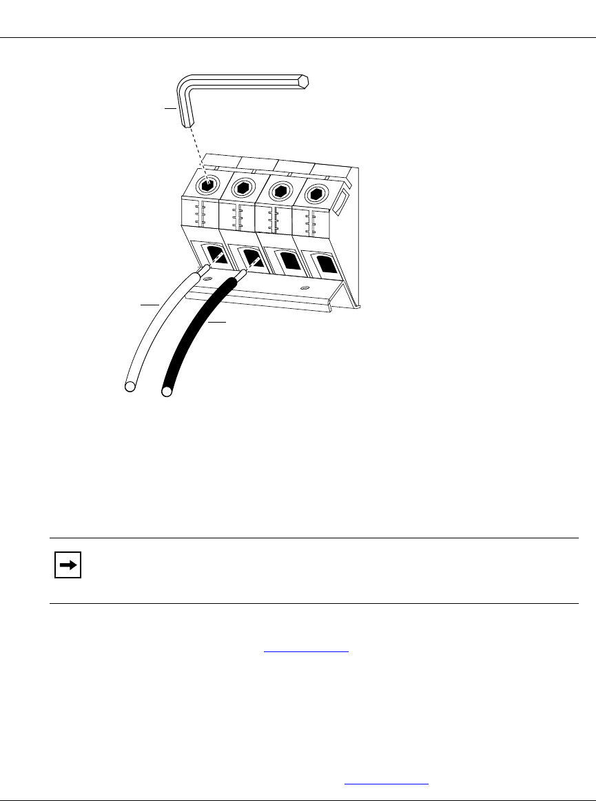
Figure 3-10. Attaching the DC Input Leads
5.
Strip 0.80 in. (20 mm) of insulation from the end of an AWG #2 or #4
wire.
6.
Attach the negative lead (-VDC-A input) from the power source to the
-VDC terminal block (Figure 3-10)
.
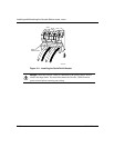
7.
Strip 0.80 in. (20 mm) of insulation from the end of an AWG #2 or #4
wire.
8.
Attach the positive lead (-VDC RTN-A) from the power source to the
-VDC RTN terminal block.
9.
Using a 5/32 in. hex wrench, tighten the 2 screws on the terminal block to
establish the electrical connection (Figure 3-10)
.
Note:
Although AWG #4 wiring is adequate for the input leads, Nortel
Networks recommends AWG #2 to ensure minimal voltage drop from the
power source.
Black cable
to RTN
White cable
to -VDC
Hex wrench
VRS0048A
-VDC RTN -VDC RTN