


36 Chapter 5 Initializing the CallPilot Mini/CallPilot 150
P0990474 03
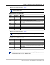
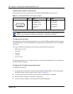
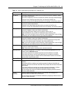
CallPilot Mini/CallPilot 150 serial port
The following table shows the pin out for the CallPilot Mini/CallPilot 150 serial port.
Configuring the terminal
The terminal or terminal emulation program you use must be VT100 compatible and must support
the ASCII Character set. If the terminal does not support the ASCII Character set, the text displays
incorrectly.
You must configure your terminal to the following communications parameters:
• 9600 bits per second
• 8 data bits
• no parity
•1 stop bit
• no flow control
For information about how to set these parameters, refer to the documentation for your terminal or
terminal emulation program.
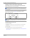
Changing the IP address using the terminal
To change the IP address:
1 Attach the serial cable to the serial port on the CallPilot Mini/CallPilot 150. For information
about the location of the serial port, refer to Figure 3 on page 25.
2 Attach the other end of the cable to the serial port on the terminal or computer.
3 Ensure that your terminal or computer is powered up.
4 If you are using a computer, start your terminal emulation program.
Table 12 CallPilot Mini/CallPilot 150 serial port pinout
Pin Signal Pin Signal
1 No connection 6 No connection
2 Serial data in (RX) 7 No connection
3 Serial data out (TX) 8 No connection
4 No connection 9 No connection
5Ground
Note: The location of the transmit (TX) and receive (RX) pins on your terminal can vary.
Refer to your terminal or computer documentation to confirm pin locations.
1 2 3 4 5
6 7 8 9