


Installation and Setup Chapter 2
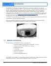
SMART-AG User Manual Rev 2 21
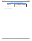
Table 2: SMART-AG Connector Pin-Out
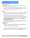
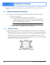
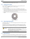
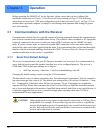
3. Turn on the power supply to the SMART-AG (the SMART-AG cable is also a power cable). The
power LED on the back of the receiver glows red when the SMART-AG is properly powered.
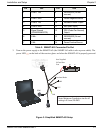
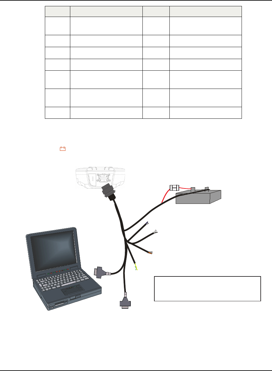
Figure 3: Simplified SMART-AG Setup
Pin Use Pin Use
1 COM 1 TxD 8 RESERVED (Do not
connect)
2 COM 1 RxD 9 Power Negative/Return
3 COM 2 TxD 10 Emulated Radar Output
4 COM 2 RxD 11 MKI (Mark Input)
5 Signal Ground
(COM/ER/MKI/PPS)
12 PPS (Pulse Per Second)
Output
6 CAN+ 13 RESERVED (Do not
connect)
7 CAN- 14 Power Positive/Source
+
-
Emulated Radar
MKI
PPS
CAN
COM
COM
User Supplied
5A Fast Blow
Fuse
Note: Minimum Conductor size for all
wiring is 0.5 mm/20 AWG