


Technical Specifications Appendix A
SMART-AG User Manual Rev 2 53
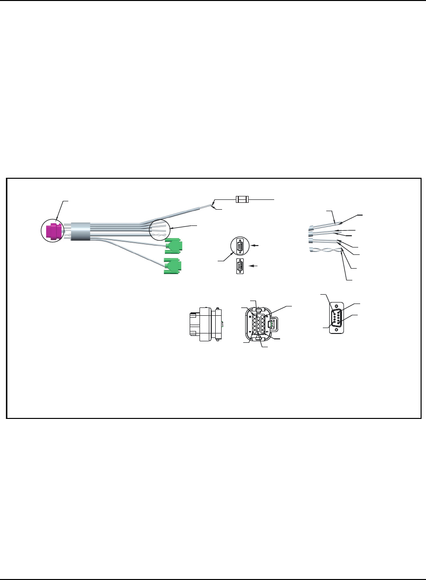
A.2.1 SMART-AG Power/Communications Development kit Cable
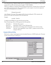
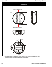
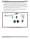
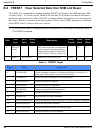
The SMART-AG cable that accompanies the SMART-AG, see Figure 15 below, provides a means of
supplying power from a battery while operating in the field. The exposed wires (red for positive and
black for negative) can then be connected to a 12 or 24V vehicular power circuit (or equivalent)
protected by a 5A fast blow fuse (user supplied). The cable also has two DB-9 connectors. One can
accommodate a PC/laptop serial (RS-232) communication port and the other can connect to a modem
or radio transmitter to propagate differential corrections (please refer to your user-supplied modem or
radio transmitter user guide for more information on its connectors).
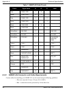
In addition, there are a number of bare wires where the outer insulation is cut away but the wires
beneath are intact. See Table 7 on Page 54 for their pinouts. For more information on mating
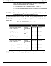
connectors and part numbers, see Table 8 on Page 55.
This cable is RoHS compliant and its part number is 01018256.
Figure 15: SMART-AG Development Kit Cable
J2
J3
J1
0.500SCALE
SEE DETAIL A
SEE DETAIL B
RED,
BATT +
BLACK
BATT-
STRIP INSULATION FROM
12 WIRES AND CRIMP AMP/TYCO
TERMINAL # 770520-3 OR 770854-3
PER TYCO APPLICATION SPEC
114-16016
1.000SCALE
ADETAIL
BLUE,
ER_OUT
WHT-BLK,
ER GND
WHITE, MKI
WHT-BLK,
MKI GND
ORANGE, PPS
WHT BLK,
PPS GND
YELLOW,
CAN1+
GREEN,
CAN1-
1.000SCALE
BDETAIL
PIN 1
PIN 2
PIN 6
PIN 9
PIN 10
PIN 14
SEE DETAIL C
1.000SCALE
CDETAIL
PIN 5
PIN 1
PIN 9
PIN 6
COM 1
COM 2
5A Fast Blow Fuse
(User Supplied)