


Installation and Setup Chapter 2
SMART-AG User Manual Rev 2 23
tape attached, or mounting holes at each corner of the plate.
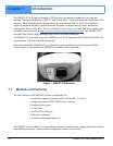
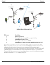
2.1.5 Mounting the SMART-AG
The SMART-AG is a single-frequency GNSS receiver and antenna.
When installing the SMART-AG:
• Choose a location that has a clear view of the sky so that each satellite above the
horizon can be tracked without obstruction. (Refer to the Multipath section in the
GPS+ Reference Manual).
• Mount on a secure, stable structure capable of safe operation in the specific
environment. Typical installation is the tractor cab roof, ideally on the steering point
of the tractor.
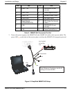
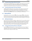
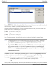
2.1.6 Connecting Data Communications Equipment
In order to communicate with the receiver, by sending commands and obtaining logs, a connection to
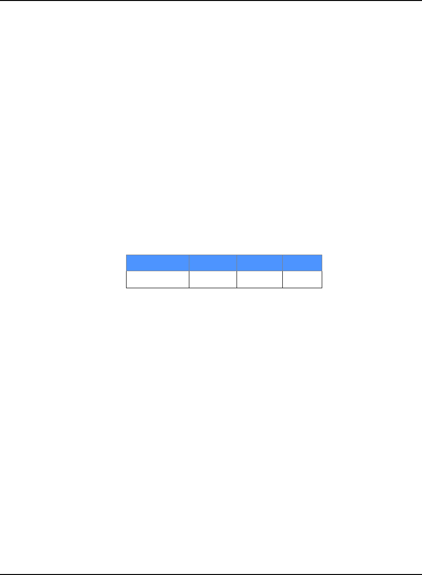
some form of data communications equipment is required. The default configuration available is
shown in Table 3, below, and its pin-out table is in Appendix A on Page 54.
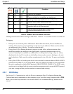
Table 3: Default Port Configurations
2.2 Additional Features and Information
This section contains information on the additional features of the SMART-AG, which may affect the
overall design of your receiver system.
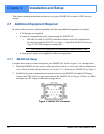
2.2.1 MKI and PPS Strobes
An input (MKI) and ouput (PPS) strobe provide status and synchronization signals. PPS is a 3.3V
CMOS output; MKI is an SV logic tolerant input.
Pin-out information can also be found on Page 54.
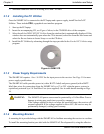
2.2.2 Status Indicators
LED indicators on the SMART-AG provide the status of the receiver. They represent these categories:
• Position Status
• Position Type
• Power
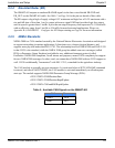
Table 4, SMART-AG LED Status Indicators on Page 24 shows the meaning of the LED states in the
expected sequence after power is applied.
Receiver COM1 COM2 CAN
SMART-AG RS-232 RS-232 CAN