


38 SMART-AG User Manual Rev 2
Chapter 4 PC Utilities
valid). Normally this represents the latency in the correction data.
• The number of satellites used in the solution
• The Solution Status
• The receiver's date and time (GMT and local)
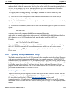
Open this window by selecting Position Window from the View menu or its button in
the Window Toolbar.
Right-click in the Position window to that enables you to set the PC clock to the receiver's time,
change the font used to display the position data or set the units through the Options dialog box.
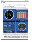
• Velocity Window: The Velocity window displays vertical and horizontal speed and direction.The
numeric displays within the dial, and the velocity values below the dial, show the vector velocity
as well as the vertical, North, and East velocity components. If necessary, the scale in the dial
increases so that you have room to accelerate.
Open this window by selecting Velocity Window from the View menu or its button in
the Window Toolbar.
• Compass Window: The direction dial is a compass that displays the direction of motion of the
receiver over ground and its elevation (both in degrees). The white arrow indicates the elevation
value on the vertical scale down the centre of the dial. The black arrow on the outer rim of the dial
indicates the Track Over Ground value. Both the track over ground and elevation angles are also
shown at the bottom of the Compass window.
Open this window by selecting Compass Window from the View menu or its button in
the Window Toolbar.
• INS Window: If applicable, please refer to your SPAN User Manual for more on INS.
Information in the INS Position, Velocity, Attitude window is only available if you have an INS-
capable receiver model.
The dial is a graphical display of the Roll, Pitch and Azimuth values indicated by an arrow on
each axis.
Open this window by selecting INS Window from the View menu or its button in the
Window Toolbar.
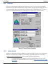
• Plan Window: The Plan window provides real-time graphic plotting of the current position of
each connected device. The latitude and longitude shown at the bottom of the window indicate
the receiver's reference position, which is used as the center of the grid system. The receiver's