


196
CrossFire 8600/8605 Token-Ring Switches v. 1.2, P/N: 710001641 Troubleshooting
4. Observe the LEDs on the switch front panel. Figure 3 on page 5 illustrates the
LEDs. For explanations of the LEDs, see the section “Status and Activity
LEDs” on page 8. Review this section before proceeding with the
troubleshooting process.
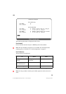
5. In Table 23, locate the symptom that best describes the communication problem
and the LED pattern you observed. Then, go to the section that contains the
recommended actions for resolving the problem and follow that procedure.
Choosing a Troubleshooting Procedure
Use Table 23 to determine which troubleshooting procedure you should use. For a
description of the status LEDs and their meanings, see “Status and Activity LEDs”
on page 8.
Procedure A
Use this procedure if all of the LEDs are off:
1. Verify that the power cord is connected at both ends and that the power outlet is
working.
2. If the power cord is connected correctly, the outlet is working, and the problem
persists, the problem is in the switch. In that case, contact technical support as
described in Chapter 11, “Getting in Touch with Technical Support”.
Symptom and LED State Go To:
All of the LEDs are off. Procedure A
The ERR LED or the DIAG are on. Procedure B
None of the devices connected to the switch
can communicate, the ERR LED is off, and
the PWR LED is on.
Procedure C
A single device connected to the switch is
having trouble communicating.
Procedure D
The ERR LED on an expansion module is
on, or a device connected to an expansion
module is experiencing problems.
See the troubleshooting
section in the expansion
module documentation.
➽ Note:
Segment refers to a single cable or interconnected cables between
a switch port and the device at the other end.
Table 23. Symptom, LED State and Recommended Procedure