


17
CrossFire 8600/8605 Token-Ring Switches v. 1.2, P/N: 710001641 Switch Theory of Operation
2. Switch Theory of Operation
This chapter explains how the CrossFire 8600 Token-Ring Switch and/or the
CrossFire 8605 Token-Ring Fiber Switch improve network performance.
The topics of this chapter are presented under the following titles:
•
“How the CrossFire 8600 and the CrossFire 8605 Works”, starting on page 17.
•
“Benefits of the CrossFire 8600 and the CrossFire 8605”, starting on page 32.
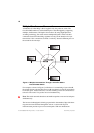
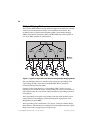
How the CrossFire 8600 and the CrossFire 8605 Works
The CrossFire 8600 and the CrossFire 8605 are both IEEE 802.5-compliant devices
designed to boost throughput on Token-Ring networks. They operate as a Media
Access Control (MAC)-layer device that is protocol independent.
This chapter describes how the switch operates as a single stand-alone unit. The
switch contains the following main elements, as listed below:
•
Switching Bus—the architecture of the switch centers around the AXIS bus, a
520 Mbps switching fabric through which all switched ports communicate.
The AXIS bus is a partially asynchronous time division multiplexed bus used
for switching packets between heterogeneous LAN modules.
•
Token-Ring Ports—each port can attach to a classical Token-Ring segment or
to a dedicated station. Now users running basic applications are able to share
bandwidth, and users running bandwidth-intensive applications can receive
their own dedicated 16 Mbps port. Each dedicated port can also be set up in
full-duplex communication mode, so that each 16 Mbps port doubles to 32
Mbps.
•
Expansion Modules—each switch supports two expansion modules. These
modules include RJ-45 or fiber ports to provide up to eight additional 16 Mbps
ports, or high-speed connections such as 155 Mbps ATM, to provide two ATM-
Ring connections for servers or backbone connectivity.
•
Stack Link Module—the switch supports a stack link module that can be used
to connect two switches from the CrossFire 8600 series in a back-to-back
configuration. Alternatively, up to five switches can be connected together
using and internal stacker module, and up to eight switches can be connected
together using the stack link module and an additional switch stack unit. By
connecting switches together through the stack link module, the switches
virtually combine to form a single unit, providing scalability, simplified
management, and enhanced performance.