113
Setting Data Links Section 5-2
5-2 Setting Data Links
5-2-1 Selecting Manual or Automatic Setting
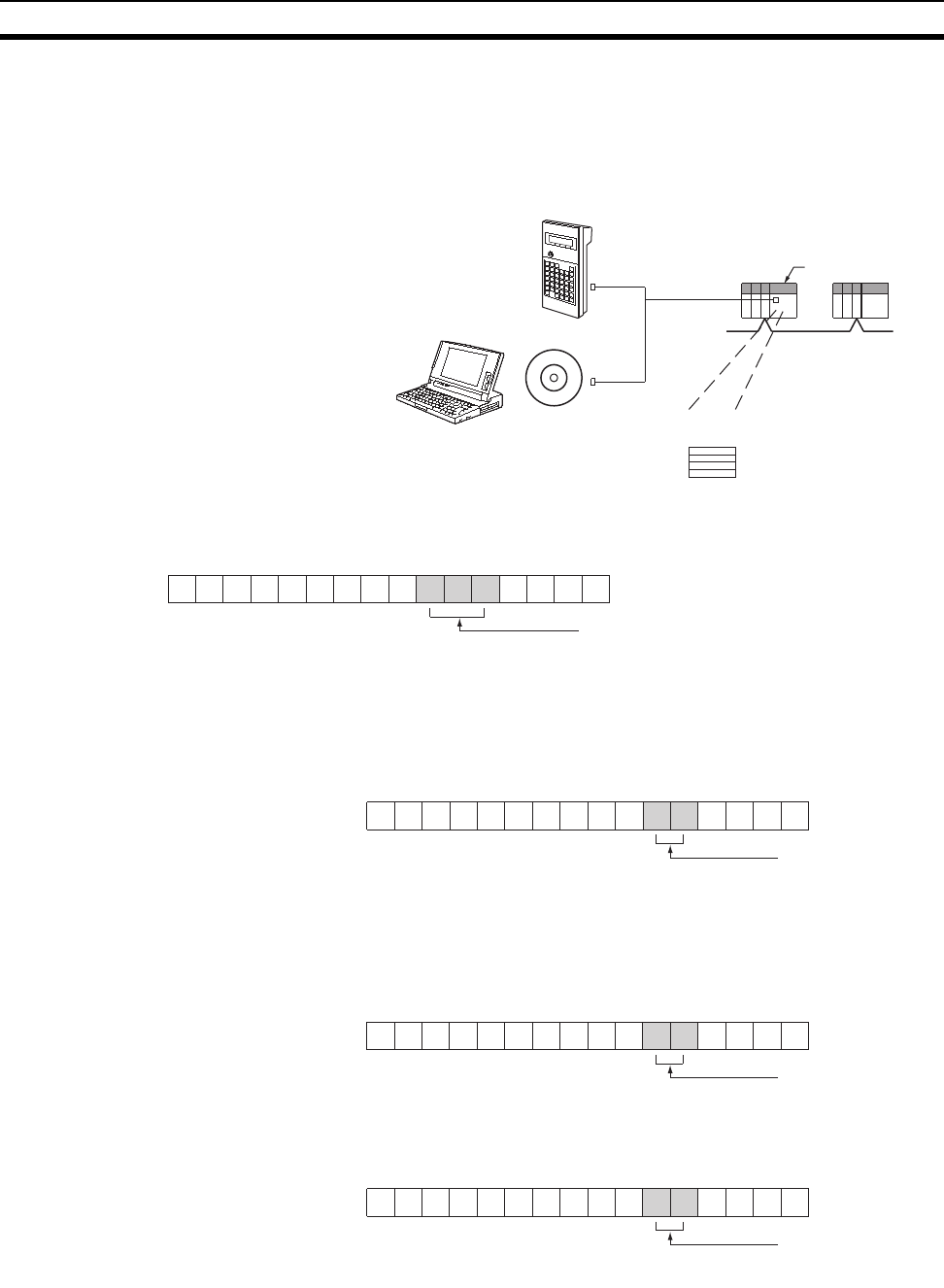
Specify either the manual or automatic data link mode in the following DM
Parameter Area of the PLC’s CPU Unit of the startup node, using a PLC Pro-
gramming Device.
CS/CJ-series Startup Nodes
C200HX/HG/HE Startup Nodes
CVM1 and CV-series Startup Nodes
CQM1H-series Startup Nodes
Software switches
(DM area)
Startup node
CPU Unit
Or
Programming Console
CX-Net in CX-
Programmer
IBM PC/AT or
compatible
Controller Lin
k
N: DM 30000 + 100 x Unit number of Controller Link Unit
Word N
0: Always 0.
–: Other setting
Data link mode
000: Manual setting
001: Automatic setting, equality layout
15 14 13 12 11 10 9 8 7 6 5 4 3 2 1 0
––
00–000– 000
–
101: Automatic setting, 1:N allocation
N: Level 0 = DM 6400
Level 1 = DM 6420
0: Always 0.
–: Other settings
Data link mode
00: Manual setting
01: Automatic setting
15 14 13 12 11 10 9 8 765 4 3 2 1 0
Word N
––
0
–
000000 0000
N: DM 2000 + 100 x unit number of Controller Link Unit
Word N
0: Always 0.
–: Other setting
Data link mode
00: Manual setting
01: Automatic setting
15 14 13 12 11 10 9 8 765 4 3 2 1 0
––
00000000 000
–
DM 6400
0: Always 0.
– : Other setting
Data link mode
00: Manual setting
01: Automatic setting
15 14 13 12 11 10 9 8 765 4 3 2 1 0
––
0
–
000000 0000


