293
Status Area and Troubleshooting Section 9-2
9-2-1 CS/CJ-series Controller Link Units
The status of the Unit and Network is indicated in the following manner in the
PLC.
Status Area
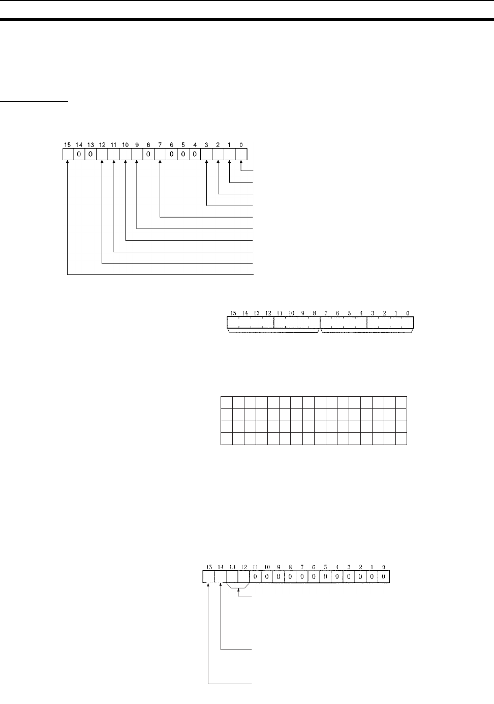
Error Information:
CIO 1500 + 25 x (Unit No.)
Polling Node Address, Startup Node Address: CIO 1500 + 25 x (Unit No.) + 1
Network Participation Status: CIO 1500 + 25 x (Unit No.) + 2, + 3
Local Data Link Participation Status: CIO 1500 + 25 x (Unit No.) + 6
1: Network parameter error (In PLC's EEPROM)
1: Data link table error (in PLC's EEPROM)
1: Routing table error (in PLC's EEPROM)
1: PLC system setting error
1: EEPROM error
1: Duplicate node address setting error
1: Inconsistent network parameters
1: Communications controller send error
1: Communications controller hardware error
1: Error log exists
Polling node address Startup node address
Each node address is displayed in 2-digit BCD.
The numbers in the squares are node addresses.
The corresponding node participation status is as follows:
0: Not participating in network
1: Participatin
g
in network
+ 2
+ 3
15 14 13 12 11 10 9 8 7 6 5 4 3 2 1 0
16 15 14 13 12 11 10 9 8 7 6 5 4 3 2 1
32 31 30 29 28 27 26 25 24 23 22 21 20 19 18 17
+ 4
48 47 46 45 44 43 42 41 40 39 38 37 36 35 34 33
+ 5
−−62 61 60 59 58 57 56 55 54 53 52 51 50 49
When CS1W-CLK21-V1 and CJ1W-CLK21-V1 Units are
used and the Wired Network 62 Node Enable Bit in the DM
Parameter Area software switches is ON, the network
participation status of nodes 33 to 62 will be returned in
words +4 and +5.
1: Local node data link participating
0: Local node data link not participating or data link
inactive
Allocation for automatic setting
00: Equality layout
01: 1:N allocation, common type
10: 1:N allocation, 1 to 1 type
11: 1:N allocation, chain type
Data link mode
0: Manual setting
1: Automatic setting


