266
Message Delay Times Section 8-4
Note Be sure to take into account the time required for data links and program exe-
cution, which are not included in the following example.
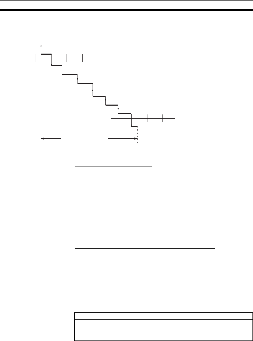
Max. transmission delay = Link Unit servicing interval (source node) + Link
service processing (source node) + Transmission processing + Communica-
tions cycle time + Transmission delay + Reception processing + Link Unit ser-
vicing interval (destination node) + Link service processing (destination node)
Link Servicing Interval (Source and Destination Nodes)
Link servicing depends on the execution mode of the PLC. The execution
modes on the source and destination modes need not be the same.
For synchronous execution, links are serviced once per PLC execution cycle.
For asynchronous execution, links are serviced according to the peripheral
servicing interval. Refer to the operation manual for the PLC for details. Refer
to the CVM1 and CV-series PLCs Operation Manual: Ladder Diagrams
(W202) or CS/CJ-series PLCs Instructions Reference Manual (W340) for
details.
Link Service Processing (Source and Destination Nodes)
Link service processing is the same as the PLC’s peripheral servicing and is
approximately 1 ms for Controller Link Units.
Transmission Processing
Number of words transferred × 0.00075 ms + 2 ms
Communications Cycle Time (with Data Links Inactive)
See 8-2 Communications Cycle Time (on page 251).
Transmission Delay Time
Transmission delay time varies with the baud rate.
SEND(192)/SEND(90)
executed
Link Unit servicing (source node)
Transmission processing
Communications cycle
Data stored
Reception processing
Max. transmission delay
Link Service processing (source node)
Link Service processing
(destination node)
Transmission delay
Link Service
processing
(source node)
Baud rate Transmission delay time
2 Mbps Number of words transferred × 0.008 + 0.112 ms
1 Mbps Number of words transferred × 0.016 + 0.224 ms
500 Kbps Number of words transferred × 0.032 + 0.448 ms


