334
Adding Nodes Using a Repeater Unit Section 10-1
• If automatic settings are used, make sure that the appropriate DM Area
parameters have been set.
Check that the new data transmission that will be performed due to the new
nodes has been considered in the user program for the existing network
before adding the nodes. If the ladder program is not suitable, the system may
not operate properly.
Make sure that the node addresses of the new nodes are not already being
used by other nodes in the same network. If the same node address is used
by more than one node, a node duplication error will be detected when the
node is added, communications will stop, and the node with the same address
will not be able to the join the network. Data may also be unexpectedly
received from the incorrectly set node. To restore a Controller Link Unit with a
duplicated address, reset the node address correctly, then turn ON the power
to the corresponding PLCs again, or restart the Controller Link Units.
Always set the baud rate of the new nodes and the Repeater Unit to the same
baud rate used for the existing network. If a different baud rate is set when
adding a new node, the communications for the whole network including the
existing network will be unstable and communications errors will occur.
Set the terminating resistance of the new nodes to the Repeater Unit as
shown in the following diagram. If terminating resistance is set incorrectly,
communications errors may occur.
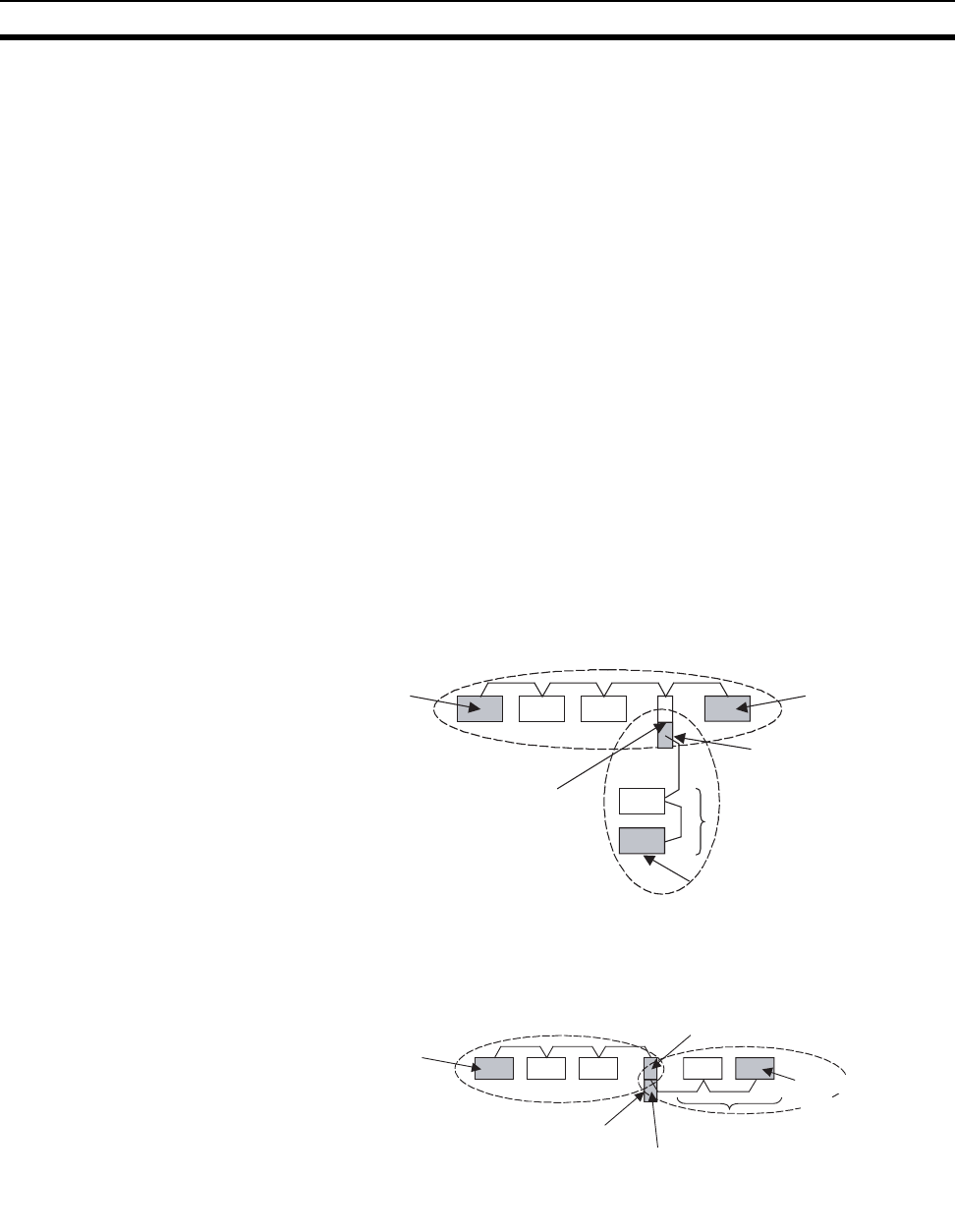
• Adding Nodes Using T-branch Lines
• Adding Nodes with a Repeater Unit at One End
System Configuration after Adding Nodes
Terminating
resistance ON
Terminating
resistance ON
CS1W-RPT01
Repeater Unit
Terminating
resistance ON
Newly added nodes
Terminating
resistance ON
Turn ON terminating resistance at the
nodes on both ends of each segment
shown within broken lines.
Terminating
resistance ON
Terminating
resistance ON
Terminating
resistance ON
CS1W-RPT01
Repeater Unit
Newly added nodes
Terminating
resistance ON
Turn ON terminating resistance at
the nodes on both ends of each
segment shown within broken lines.


