About Your Projector
18
- ENGLISH
Preparation
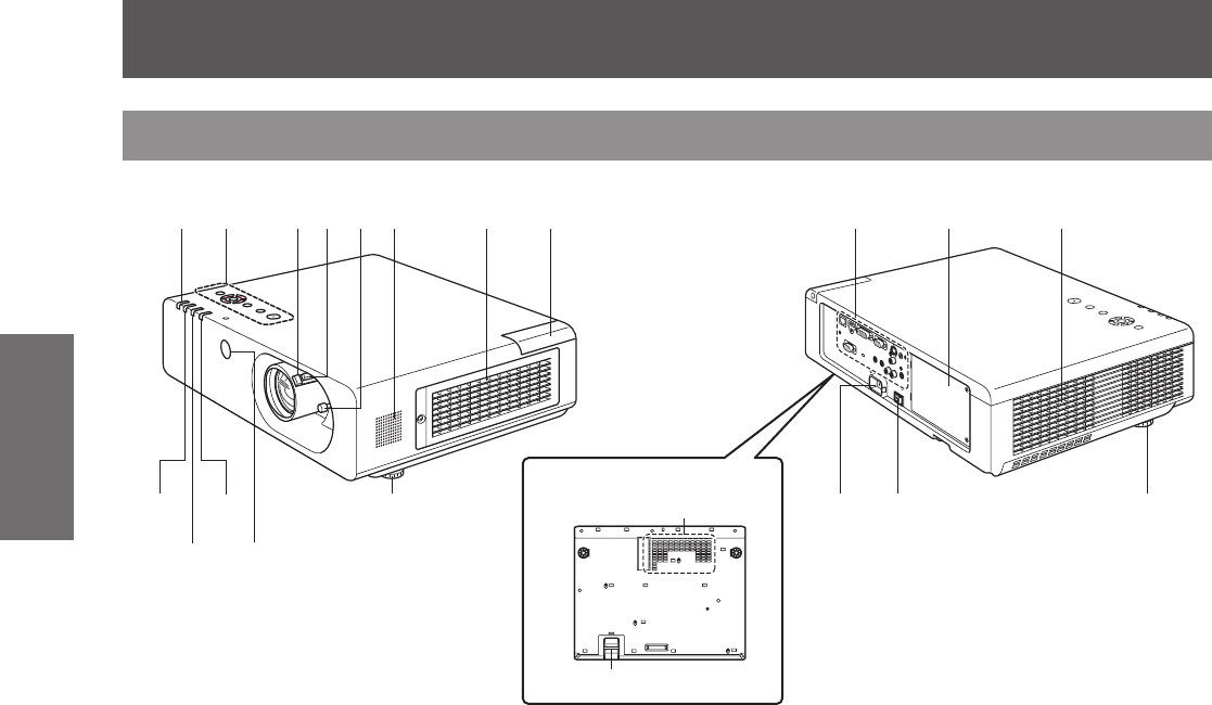
(1) Power indicator (STANDBY(R) / ON(G))
Indicates the power supply status
(2) CONTROL PANEL (
Æ
page 19)
(3) Focus lever
Adjusts the focus.
(4) Zoom lever
Adjusts the zoom.
(5) Lens shift lever
Adjusts the position of the projected image.
(6) Speaker
(7) Air intake port / Air lter cover
The air lter unit is located inside. (
Æ
page 70)
(8) Wireless module cover
The wireless module connection terminal is
located inside. (
Æ
page 74)
(9) Lamp indicator (LAMP)
Indicates the lamp unit status.
(10) Temperature indicator (TEMP)
Indicates the temperature status inside of the
projector.
(11) Filter indicator
Indicates the state of the air lter unit.
(12) Remote control signal receiver (front)
(13) Front adjustable feet
Adjusts the projection angle.
(14) Rear terminals (
Æ
page 19)
(15) Lamp cover (
Æ
page 73)
The lamp unit is located inside.
(16) Air exhaust port
(17) AC IN terminal
Connects to the supplied power cord.
(
Æ
page 28)
(18) <MAIN POWER> switch
Turns the MAIN POWER to [ON]/[OFF].
(19) Air intake port
(20) Security bar
Attach an anti-theft cable here.
WARNING:
Keep your hands and other objects away
■
from the air exhaust port.
Keep your hand and face away.
z
Do not insert your nger.
z
Keep heat-sensitive articles away.
z
Heated air from the air exhaust port can cause burns
or external damage.
Projector body
■
Bottom view
(9)
(10)
(11)
(12)
(13)
(19)
(20)
(17) (18) (13)
(1)
(2)
(3)
(4)
(5)
(6)
(7)(8)
(14)
(15)
(16)


