


Hotwire Menus and Screens
2-3
8000-A2-GB20-50
April 2000
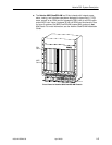
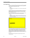
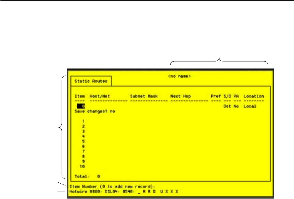
Components of a Hotwire Screen
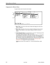
A typical Hotwire screen looks like this:
2
1
4
3
1. System Header Line is the top line of the screen. This line has two fields
that provide system login information.
— The first field displays the chassis name or the individual card name.
(Access the System Information screen by selecting the appropriate card
in the chassis and then follow this menu sequence: Configuration →Card
Status →Card Info.) If you do not define the system name, the DSL user
interface will display <no name>.
— The second field displays the current login. This field will display either
L:<user_login> or R:<user_login> where L indicates a local login,
R indicates a remote login, and <user_login> is the login account of
the user currently accessing the system. For example, if a user with a
login account called admin logs into the system using the local console,
this field will display L:admin.
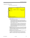
2. Display Area is the top portion of the screen on which pertinent DSL system
information is displayed. This is also the portion of the screen on which fields
requiring input are displayed. However, you cannot enter values for the fields
in this portion of the screen. You must enter field values in the Input Line at
the bottom of the screen (see #3 below).
3. Input Line is the area of the screen where you are prompted to enter values
for the specific field that is highlighted on the screen.
For example, in the Static Routes screen above, the Item Number field is
highlighted. If you want to add a new record, you must enter 0 at the item
number (0 to add new record): prompt at the bottom of the screen.