


DMD15/DMD15L IBS/IDR Satellite Modem User Interfaces
TM051 - Rev. 5.8 4-71
<30>
<1>
<1>
<1>
<1>
<1>
<1>
<11>
<1>
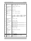
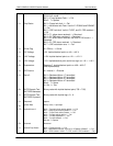
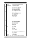
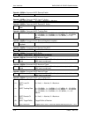
Drop Map
T1D4 Yellow Alarm
Sel.
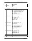
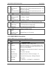
Forced Alarms
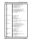
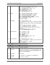
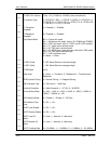
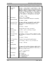
Alarm 1 Mask
Alarm 2 Mask
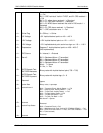
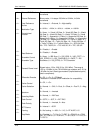
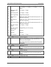
Common Alarm 1
Mask
Common Alarm 2
Mask
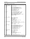
Tx Circuit ID
Tx ESC Ch 1 Volume
Timeslots to drop organized by satellite channel
0 = Bit 2 equal 0 for all channels
1 = Frame 12 s-bits equal 1)
(0 = None, or else a 1 in the following bits means force)
Bit 0 = Backward Alarm 1 IDR and IBS
Bit 1 = Backward Alarm 2 IDR only
Bit 2 = Backward Alarm 3 IDR only
Bit 3 = Backward Alarm 4 IDR only
Bit 4 = AIS Request
Bit 5 = T1D4 Yellow Alarm. D&I Mode
Bits 6 and 7 = Spares
Bit 0 = Transmit processor Fault
Bit 1 = Transmit output power level Fault
Bit 2 = Transmit Oversample PLL lock
Bit 3 = Composite clock PLL lock
Bit 4 = IF synthesizer lock
Bit 5 = IDR 96 PLL lock
Bit 6 = RS FIFO fault
Bit 7 = Mod Summary fault
0 = Mask, 1 = Allow
Bit 0 = Terrestrial clock activity detect
Bit 1 = Internal clock activity detect
Bit 2 = Tx Sat clock activity detect
Bit 3 = Tx data activity detect
Bit 4 = Tx data AIS detect
Bit 5 = Tx clock fallback
Bit 6 & 7 = Spares
0 = Mask, 1 = Allow
Bit 0 = -12V alarm
Bit 1 = +12V alarm
Bit 2 = +5V alarm
Bit 3 = Reserved
Bit 4 = Battery
Bit 5 = RAM and ROM alarm flag
Bits 6 and 7 = Spares
0 = Mask, 1 = Allow
Bit 0 = M&C processor fault
Bit 1 = U IO card present, reserved in RCS10/10L mode
Bit 2 = IF card present
Bits 3 - 7 = Spares
0 = Mask, 1 = Allow
11 ASCII characters
-20 to +10 (+10 dBm to –20 dBm) (two’s compliment)