


DMD15/DMD15L IBS/IDR Satellite Modem User Interfaces
TM051 - Rev. 5.8 4-45
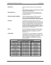
<SOURCE ID>: The Source Identifier defines the multi-drop address
origin.
Note: All nodes on a given control bus have a unique
address that must be defined.
<DESTINATION ID>: The Destination Identifier serves as a pointer to the
multi-drop destination device that indicates where the
message is to be sent.
<FRAME SEQUENCE NUMBER>: The Frame Sequence Number (FSN) is a tag with a
value from O through 255 that is sent with each
message. It assures sequential information framing and
correct equipment acknowledgment and data transfers.
<OPCODE>: The Operation Code field contains a number that
identifies the message type associated with the data that
follows it. Equipment under MCS control recognizes this
byte via firmware identification and subsequently steers
the DATA accordingly to perform a specific function or
series of functions. Acknowledgment and error codes are
returned in this field. 1 Byte for the DMD5000 protocol,
and 2 Bytes for the DMD15 protocol.
<DATA >: The Data field contains the binary, bi-directional data
bytes associated with the <OPCODE>. The number of
data bytes in this field is indicated by the <BYTE
COUNT> value.
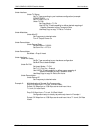
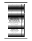
<CHECKSUM>: The checksum is the modulo 256 sum of all preceding
message bytes, excluding the <SYNC> character. The
checksum determines the presence or absence of errors
within the message. In a message block with the
following parameters, the checksum is computed as
shown in Table 4-7.
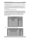
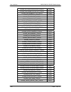
Table 4-7. Checksum Calculation Example
BYTE FIELD DATA CONTENT RUNNING CHECKSUM
<BYTE COUNT> (Byte 1) 00h = 00000000b 00000000b
<BYTE COUNT> (Byte 2) 02h = 00000010b 00000010b
<SOURCEID> F0h = 11110000b 11110010b
<DESTINATION ID> 2Ah = 00101010b 00011100b
<FSN> 09h = 00001001b 00100101b
<OPCODE> (Byte 1) 00h = 00000000b 00100101b
<OPCODE> (Byte 2) 03h = 00000011b 00101000b
<DATA> (Byte 1) DFh = 11011111b 00000111b
<DATA> (Byte 2) FEh = 11111110b 00000101b