


DMD15/DMD15L IBS/IDR Satellite Modem User Interfaces
TM051 - Rev. 5.8 4-43
multiframe alignment signal and therefore channels 1 through 30 are mapped to time slots 1
through 16 and 17 through 31.
4.8 Terminal Mode Control
The DMD15/DMD15L Terminal Mode Control allows the use of an external terminal or computer
to monitor and control the modem from a full screen interactive presentation operated by the
modem itself. No external software is required other than VT100 Terminal Emulation Software
(e.g. “Procomm” for a computer when used as a terminal. The Control Port is normally used as
an RS–232 Connection to the terminal device. The RS-232 operating parameters can be set
using the modem Front Panel and stored in EEPROM for future use.
4.8.1 Modem Terminal Mode Control
The modem can be interactively monitored and controlled in the Terminal Mode, with a full screen
presentation of current settings and status. Programming is accomplished by selecting the item to
be modified and pressing the terminal key of the option number. For example, to change the
transmit data rate, enter ‘33’ at the terminal. The modem will respond by presenting the options
available and requesting input. Two types of input may be requested. If the input is multiple
choice, the desired choice is selected by pressing the ‘Space’ key. When the desired option is
displayed, press the ‘Enter’ key to select that option. The other possible input type requires a
numerical input (such as entering a frequency or data rate. This type of input is followed by
pressing the ‘Enter’ or carriage return key. An input can be aborted at any time by pressing the
‘ESC’ key. Invalid input keys cause an error message to be displayed on the terminal.
The Terminal Control Mode supports serial baud rates of 150, 300, 1200, 2400, 4800, 9600,
19200, and 38400. The connection must be set for 8 data bits, 1 stop bit and no parity (8,N,1).
Three terminal emulations are supported: VT100, WYSE 50, and ADDS-VP.
“$” is used for setting the screen when the terminal is used is used for the first time or the non-
volatile memory gets reset.
4.8.2 Modem Setup for Terminal Mode
Terminal Mode Communications and Protocol is set from the Front Panel Control by setting the
“Control Mode” Parameter to “Terminal”, and then setting the “Modem Port”, “Term Baud” and
“Emulation” Parameters as desired. Then a terminal is connected to Connector J5 on the Back
Panel. All operating software for the Terminal Mode is contained within the DMD15/DMD15L
Modem Internal Control Software.
A “break” signal on the communications line, pressing “ESC” on the terminal or Power On of the
modem will initiate full screen terminal mode printing and redraw the full screen. The Terminal
Mode displays the present status of all user parameters controlled and read by the processor, and
offers a menu allowing change to any controlled parameter.
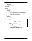
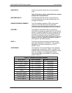
The Terminal Mode uses eight “Screens,” each of which have the basic contents of the three
modem monitor and control areas as set in the Front Panel matrix columns. This screen is used
for setting the parameters of the Modulator, Demodulator, Event, Alarm, Latched Alarm, Drop
Controls, Insert Controls, and Interface Areas.