


User Interfaces DMD15/DMD15L IBS/IDR Satellite Modem
4-72 TM051 – Rev. 5.8
<1>
<1>
<1>
<1>
<1>
<1>
<1>
<1>
<1>
<1>
<1>
<1>
<1>
<1>
<1>
<1>
<1>
<1>
<1>
<1>
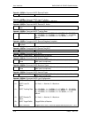
Tx ESC Ch 2 Volume
Tx Interface Type
Tx Terrestrial
Loopback
Tx Baseband
Loopback
Drop Status Mask
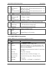
Tx RS N Code
Tx RS K Code
Tx RS Depth
Data Invert
BPSK Symbol Pairing
IDR Overhead Type
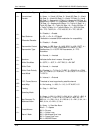
Terminal Emulation
Terminal Baud Rate
FM Orderwire Mode
FM Orderwire Test
Tone
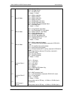
AUPC Local Enable
AUPC Remote Enable
AUPC Local CL
Action
AUPC Remote CL
Action
AUPC Tracking Rate
-20 to +10 (+10 dBm to –20 dBm) (two’s compliment)
0 = G703-B-T1-AMI, 1 = G703-B-T1_B8ZS, 2 = G703-B-E1, 3
= G703-B-T2, 4 = G703-U-E1, 5 = G703-U-T2, 6 = G703-U-E2,
7 = RS-422, 8 = V.35, 9 = RS-232
0 = Disabled, 1 = Enabled
0 = Disabled, 1 = Enabled
Bit 0 = Frame lock mask
Bit 1 = Multiframe lock mask. Valid in E1 PCM30 and PCM30C
Bit 2 = CRC lock mask. Valid in T1ESF, and E1 CRC enabled
Bit 3 = T1 yellow alarm received mask
Bit 4 = E1 FAS alarm received mask
Bit 5 = E1 MFAS alarm received mask. Not valid in FAS mode
Bit 6 = E1 CRC alarm received mask
Bit 7 = CRC calculation error
0 = Mask, 1 = Allow
2 - 255. Reed-Solomon code word length
1 - 254. Reed-Solomon message length
4 or 8
0 = None, 1 = Terrestrial, 2 = Baseband, 3 = Terrestrial and
Baseband
0 = Normal Pairing, 1 = Swapped Pairing
0 = 32K Voice. 1 = 64K Data
0 = Adds Viewpoint. 1 = VT100, 2 = WYSE50
0 = 300, 1 = 600, 2 = 1200, 3 = 2400, 4 = 4800, 5 = 9600, 6 =
19200, 7 = 38400, 8 = 150
0 = Disable, 1 = Enable, 2 = FM Only
0 = Off, 1 = On
0 = Off, 1 = On
0 = Off, 1 = On
0 = Hold, 1 = Nominal, 2 = Maximum
0 = Hold, 1 = Nominal, 2 = Maximum
0 = 0.5 dB/Min, 1 = 1.0 dB/Min, 2 = 1.5 dB/Min, 3 = 2.0 dB/Min,