


User Interfaces DMD15/DMD15L IBS/IDR Satellite Modem
4-80 TM051 – Rev. 5.8
<1>
<1>
<11>
<1>
<1>
<1>
<1>
<1>
<1>
<1>
<1>
<1>
<1>
<1>
<1>
<1>
<1>
<1>
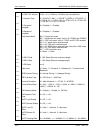
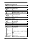
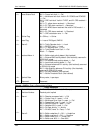
ESC Channel 2
Volume
BER Exponent
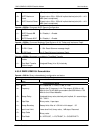
Rx Circuit ID
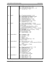
Rx Terrestrial
Loopback
Rx Baseband
Loopback
Rx IF Loopback
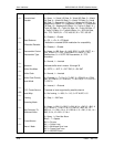
Rx Interface Type
Insert Status Mask
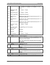
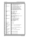
Rx Reed Solomon N
Code
Rx Reed Solomon K
Code
Rx Reed Solomon
Depth
External Clock Source
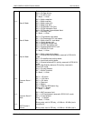
Data Invert
Alarm 5 Masks
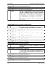
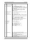
BPSK Symbol Pairing
ES Mode
ES Type
compliment)
6 through 9 for Viterbi, 5 through 7 for Sequential
11 ASCII characters
0 = Disabled, 1 = Enabled
0 = Disabled, 1 = Enabled
0 = Disabled, 1 = Enabled
0 = G703-B-T1-AMI, 1 = G703-B-T1_B8ZS, 2 = G703-B-E1, 3
= G703-B-T2, 4 = G703-U-E1, 5 = G703-U-T2, 6 = G703-U-E2,
7 = RS-422, 8 = V.35, 9 = RS-232
Bit 0 = Frame lock
Bit 1 = Multiframe lock. Valid in E1 PCM30 and PCM30C
Bit 2 = CRC lock. Valid in T1ESF, and E1 CRC enabled
Bit 3 = T1 yellow alarm received
Bit 4 = E1 FAS alarm received
Bit 5 = E1 MFAS alarm received. Not valid in FAS mode
Bit 6 = E1 CRC alarm received
Bit 7 = CRC calculation error
0 = Mask, 1 = Allow
2 - 255 Reed-Solomon code word length
1 - 254 Reed-Solomon message length
4 or 8
0 = BNC EXC, 1 = Balanced EXC, 2 = IDI, 3 = SYS [RCS10
Only]
0 = None, 1 = Terrestrial, 2 = Baseband 3 = Terrestrial and
Baseband
Bit 0 = Trellis Decoder Lock
Bit 1 = FM DSP Lock Mask
Bit 2 = T1 signaling fault
Bit 3 = Turbo Codec Lock Fault
Bits 4 - 7 = Spares
0 = Mask, 1 = Allow
0 = Normal, 1 = Swapped
0 = Normal, 1 = Enhanced
0 = RS-232, 1 = RS-485
0 = 150. 1 = 300, 2 = 600, 3 = 1200, 4 = 2400, 5 = 4800, 6 =
9600