


User Interfaces DMD15/DMD15L IBS/IDR Satellite Modem
4-40 TM051 – Rev. 5.8
4.7 D&I Maps and Map Editing
The Drop and Insert multiplexer is programmed by loading it with a transmit and receive map.
Maps always contain 30 entries, although, only the first “n” entries are relevant (see Table 4-5).
The DMD15/DMD15L includes provisions to copy, change, and store the D&I transmit and receive
maps directly from the Front Panel or via the remote M&C link. These maps are tables that are
used to define and configure the D&I functions. Each map contains up to 30 entries, which are
enough to define the channel assignments for a T1 (24 channel) or E1 (30 channel) frame
structure. Maps that are created are stored in non-volatile battery backed-up memory within the
modem and remain unchanged after a power-down.
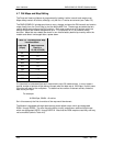
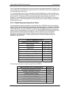
Table 4-5. D&I Multiplexer Map
Locations Used
Data Rate
(Kbps)
Map Locations
Used (n =
1,2,4,8,16,24,30)
64 1
128 1-2
256 1-4
384 1-6
512 1-8
768 1-12
1024 1-16
1536 1-24
1920 1-30
It is important to understand that each map contains up to 30 usable entries. In many cases a
smaller number of entries will be relevant, except when the data rate is 1920 Kbps, in which case
30 entries will used by the multiplexer. To determine the number of relevant entries, divide the
data rate by 64 Kbps.
For example:
At 384 Kbps, 384/64 = 6 entries.
So in this case only the first six entries of the map would be relevant.
The Modem is equipped with eight permanently stored default maps, which are designated
ROM 1 through ROM 8. The user may also define, modify, and save an additional eight maps
which are designated USER 1 through USER 8. Note that the ROM maps are read-only and may
not be modified (refer to Table 4-6).