


DMD15/DMD15L IBS/IDR Satellite Modem Installation
TM051 - Rev. 5.8 2-3
Standard DMD15/DMD15L Factory Configuration Settings
Modulator:
Data Rate: 2.048 Mbps
Mode: Closed Network
Forward Error Correction: 1/2 Rate Viterbi
Modulation: QPSK
Frequency: 70.000000 MHz
Note: The above modem configuration can be set by implementing Strap Code 26.
Refer to Table 3-1 for an explanation and tabular listing of available Strap Codes.
Modulator Output Power: -20 dBm
Demodulator:
Data Rate: 2.048 Mbps
Mode: Closed Network
Forward Error Correction: 1/2 Rate Viterbi
Frequency: 70.000000 MHz
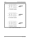
To lock up the modem, enter ‘IF Loopback Enable’ under the Test menu, or connect a Loopback
Cable from J1 to J2 on the rear panel of the modem.
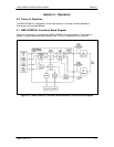
2.5 Modulator Checkout
The following descriptions assume that the DMD15/DMD15L is installed in a suitable location with
prime AC power and supporting equipment available.
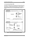
2.5.1 Initial Power-Up
Before initial power up of the DMD15/DMD15L, it is a good idea to
disconnect the transmit output from the operating ground station
equipment. This is especially true if the current Modulator Configuration
Settings are unknown, where incorrect settings could disrupt the existing
communications traffic. New units from the factory are normally shipped in
a default configuration which includes setting the transmit carrier off.
Turn on the unit by placing the Rear Panel Switch (located above the power entry connector) to
the ‘ON’ position. Upon initial and subsequent power-ups, the DMD15/DMD15L Microprocessor
will test itself and several of its components before beginning its Main Monitor/Control Program.
These power-up diagnostics show no results if successful. If a failure is detected, the Fault LED
will illuminate.