


User Interfaces DMD15/DMD15L IBS/IDR Satellite Modem
4-62 TM051 – Rev. 5.8
<1>
<1>
<11>
<1>
<1>
<1>
<1>
<1>
<1>
<1>
<1>
<1>
<1>
<1>
<1>
<1>
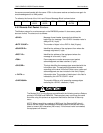
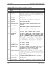
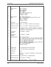
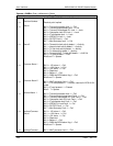
Common Alarm 1
Mask
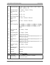
Common Alarm 2
Mask
Tx Circuit ID
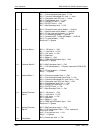
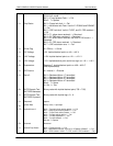
Tx ESC Ch 1 Volume
Tx ESC Ch 2 Volume
Tx Interface Type
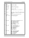
Tx Terrestrial
Loopback
Tx Baseband
Loopback
Drop Status Mask
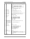
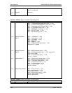
Tx RS N Code
Tx RS K Code
Tx RS Depth
Data Invert
BPSK Symbol Pairing
IDR Overhead Type
Terminal Emulation
0 = Mask, 1 = Allow
Bit 0 = -12V alarm
Bit 1 = +12V alarm
Bit 2 = +5V alarm
Bit 3 = Reserved
Bit 4 = Battery
Bit 5 = RAM and ROM alarm flag
Bits 6 and 7 = Spares
0 = Mask, 1 = Allow
Bit 0 = M&C processor fault
Bit 1 = U IO card present, reserved in RCS10/10L mode
Bit 2 = IF card present
Bits 3 - 7 = Spares
0 = Mask, 1 = Allow
11 ASCII characters
-20 to +10 (+10 dBm to –20 dBm) (two’s compliment)
-20 to +10 (+10 dBm to –20 dBm) (two’s compliment)
0 = G703-B-T1-AMI, 1 = G703-B-T1_B8ZS, 2 = G703-B-E1, 3
= G703-B-T2, 4 = G703-U-E1, 5 = G703-U-T2, 6 = G703-U-E2,
7 = RS-422, 8 = V.35, 9 = RS-232
0 = Disabled, 1 = Enabled
0 = Disabled, 1 = Enabled
Bit 0 = Frame lock mask
Bit 1 = Multiframe lock mask. Valid in E1 PCM30 and PCM30C
Bit 2 = CRC lock mask. Valid in T1ESF, and E1 CRC enabled
Bit 3 = T1 yellow alarm received mask
Bit 4 = E1 FAS alarm received mask
Bit 5 = E1 MFAS alarm received mask. Not valid in FAS mode
Bit 6 = E1 CRC alarm received mask
Bit 7 = CRC calculation error
0 = Mask, 1 = Allow
2 - 255. Reed-Solomon code word length
1 - 254. Reed-Solomon message length
4 or 8
0 = None, 1 = Terrestrial, 2 = Baseband, 3 = Terrestrial and
Baseband
0 = Normal Pairing, 1 = Swapped Pairing
0 = 32K Voice. 1 = 64K Data
0 = Adds Viewpoint. 1 = VT100, 2 = WYSE50