


User Interfaces DMD15/DMD15L IBS/IDR Satellite Modem
4-92 TM051 – Rev. 5.8
<1>
<1>
<1>
<1>
<1>
<1>
<11>
<1>
<1>
<1>
<1>
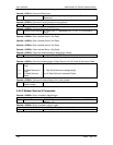
Alarm 4 Mask
Common Alarm 1
Mask
Common Alarm 2
Mask
ESC Channel 1
Volume
ESC Channel 2
Volume
BER Exponent
Rx Circuit ID
Rx Terrestrial
Loopback
Rx Baseband
Loopback
Rx IF Loopback
Rx Interface Type
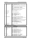
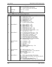
Bit 1 = Rx Oversample PLL lock detect
Bit 2 = Buffer clock PLL lock detect
Bit 3 = Viterbi decoder lock
Bit 4 = Sequential decoder lock
Bit 5 = Rx 2047 test pattern lock
Bit 6 = External reference PLL lock
Bit 7 = IDR 96K PLL Lock
0 = Mask, 1 = Allow
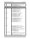
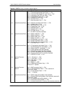
Bit 0 = Buffer clock activity detect
Bit 1 = External BNC activity detect, reserved in RCS10/10L
mode
Bit 2 = Rx satellite clock activity detect
Bit 3 = Insert clock activity detect
Bit 4 = External reference PLL activity, reserved in RCS10/10L
mode
Bit 5 = High Stability reference PLL activity, reserved in
RCS10/10L mode
Bit 6 = Rx clock fallback
Bit 7 = Eb/No Threshold
0 = Mask, 1 = Allow
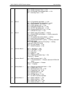
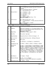
Bit 0 = -12V alarm
Bit 1 = +12V alarm
Bit 2 = +5V alarm
Bit 3 = Reserved
Bit 4 = Battery
Bit 5 = RAM and ROM alarm flag
Bits 6 and 7 = Spares
0 = Mask, 1 = Allow
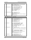
Bit 0 = M&C processor fault
Bit 1 = U IO card present, reserved in RCS10/10L mode
Bit 2 = IF card present
Bits 3 - 7 = Spares
0 = Mask, 1 = Allow
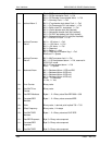
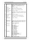
Binary value, valid in IDR only, +10 dBm to –20 dBm (two’s
compliment)
Binary value, valid in IDR only, +10 dBm to –20 dBm (two’s
compliment)
6 through 9 for Viterbi, 5 through 7 for Sequential
11 ASCII characters
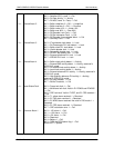
0 = Disabled, 1 = Enabled
0 = Disabled, 1 = Enabled
0 = Disabled, 1 = Enabled
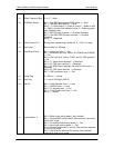
0 = G703-B-T1-AMI, 1 = G703-B-T1_B8ZS, 2 = G703-B-E1, 3
= G703
-
B
-
T2, 4 = G703
-
U
-
E1, 5 = G703
-
U
-
T2, 6 = G703
-
U
-
E2,