


DMD15/DMD15L/DMD15/DMD15LL/DMD15/DMD15LIBS/IDR Satellite Modem Maintenance
TM051 - Rev. 5.8 6-1
Section 6 – Maintenance
6.0 Periodic Maintenance
The DMD15/DMD15L modulator requires no periodic field maintenance procedures. Should a
unit be suspected of a defect in field operations after all interface signals are verified, the correct
procedure is to replace the unit with another known working DMD15/DMD15L. If this does not
cure the problem, wiring or power should be suspect.
There is no external fuse on the DMD15/DMD15L. The fuse is located on the power supply
assembly inside the case, and replacement is not intended in the field.
6.1 Troubleshooting
The following is a brief list of possible problems that could be caused by failures of the modem or
by improper setup and configuration for the type of service. The list is arranged by possible
symptoms exhibited by the modem.
Symptom: The Modem will not acquire the incoming carrier:
Possible Cause: Improper receive input to modem.
Action: Check that the receive cabling is correct.
Possible Cause: Receive carrier level too low.
Action: Check that the receive cabling is correct, that the downconverter is properly set and that
the LNA is turned on. If a spectrum analyzer is available, locate and measure the receive level,
which should not be below -65 dBm absolute, -50 dBm is nominal.
Possible Cause: Receive carrier frequency outside of acquisition range.
Action: Check that the receive acquisition range is adequate for the possible system offsets.
Setting the value to 30 kHz is a standard value encompassing all normal offsets. After
acquisition, the actual receive frequency can be read from the Front Panel.
Possible Cause: Transmit carrier incompatible.
Action: Check the receive parameter settings and ensure that they match those on the
modulator.
Possible Cause: Modem is in Test Mode.
Action: Check the modem Front Panel for yellow warning LEDs indicating a Test Mode is
enabled. Self-Test or IF Loopback disconnects the Demodulator from the IF receive input
connector.
Symptom: The Async Port is not configured correctly.
Action: Refer to Section 5.8 to correctly set switches for correct configuration.
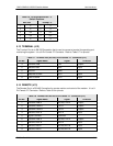
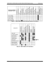
6.2 DMD15/DMD15L Fault Philosophy
The DMD15/DMD15L performs a high degree of self-monitoring and fault isolation. The alarms
are separated into three categories; Active Alarms, Common Equipment Alarms, and Latched
Alarms. In addition, a feature exists that allows the user to ‘Mask’ out certain Alarms as explained
below. Alarms that are recorded in the event buffer are the same as the alarm buffer.