


User Interfaces DMD15/DMD15L IBS/IDR Satellite Modem
4-68 TM051 – Rev. 5.8
<4>
Reserved
Bits 3-7 (not latched)
Reserved
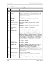
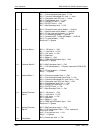
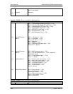
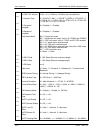
Opcode: <2405h> Query a modulator’s latched alarms
Query Response
<1>
<1>
<1>
<1>
<1>
Latched Alarm 1
Latched Common
Alarm 1
Latched Common
Alarm 2
Latched Alarm 2
Latched Drop Status
Bit 0 = Transmit processor fault. 1 = Fail
Bit 1 = Transmit output power level Fault. 1 = Fail
Bit 2 = Transmit Oversample PLL lock Fault. 1 = Fail
Bit 3 = Composite clock PLL lock Fault. 1 = Fail
Bit 4 = IF synthesizer lock Fault. 1 = Fail
Bit 5 = IDR 96 PLL Lock Fault. 1 = Fail
Bit 6 = RS FIFO Fault. 1 = Fail
Bit 7 = Mod Summary Fault. 1 = Fail
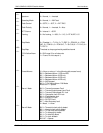
Bit 0 = -12V alarm. 1 = Fail
Bit 1 = +12V alarm. 1 = Fail
Bit 2 = +5V alarm. 1 = Fail
Bit 3 = Reserved
Bit 4 = Battery. 1 = Fail
Bit 5 = RAM and ROM alarm flag. 1 = Fail
Bits 6 and 7 = Spares
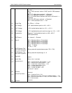
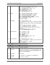
Bit 0 = M&C processor fault. 1 = Fail
Bit 1 = U IO card present Fault. 1 = Fail, reserved in
RCS10/10L mode
Bit 2 = IF card present Fault. 1 = Fail
Bits 3 - 7 = Spares
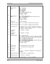
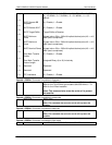
Bit 0 = Terrestrial clock activity detect. 1 = Fail
Bit 1 = Internal clock activity detect. 1 = Fail
Bit 2 = Tx Sat clock activity detect. 1 = Fail
Bit 3 = Tx data activity detect. 1 = Fail
Bit 4 = Tx data AIS detect. 1 = Fail
Bit 5 = Tx clock fallback. 1 = Fail
Bits 6-7 = Spares
Bit 0 = Frame lock fault. 1 = Fail
Bit 1 = Multiframe fault. 1 = Fail
PCM30 and PCM30C. 1 = Fail
Bit 2 = CRC lock fault. Valid in T1 ESF
And E1, CRC enabled. 1 = Fail
Bits 3-7 (Not latched)
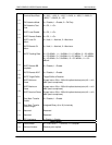
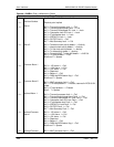
Opcode: <2408h> Query a modulator’s current alarms
Query Response
<1> Alarm 1 Bit 0 = Transmit processor fault. 1 = Fail