


Chapter 2: Installing the PowerStation Preparing for Installation
PA PowerStation User Guide 2-6
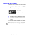
Preparing for Installation
Once you select a location for the PA PowerStation, you will need to create
a cutout for the unit.
If you plan to operate the PA PowerStation using AC power, and you
purchased Parker’s optional AC Power Supply, you will need to prepare a
location for the Power Supply also.
Procedures for creating the cutout and preparing a location for the AC
Power Supply are described below. If you already have an appropriate
cutout and are using DC power, continue with Installing the PA
PowerStation on page 2-7.
Creating the Cutout
Be sure to follow the cutout diagrams in the dimensional drawings
precisely. This ensures that the PowerStation is properly sealed in its
enclosure. You can find the dimensional drawings on the PA PowerStation
CD shipped with your unit.
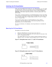
1 Measure the cutout dimensions as shown in the table below.
2 Attach the template securely to the mounting surface.
3 Cut out the shaded area on the template referred to as the Panel
Cutout Area. To ensure the flatness of the mounting surface, when
punching out the mounting hole, maintain proper surface flatness
and edge quality.
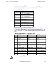
The cutout dimensions for the PA PowerStation are shown in the following
table:
4 Debur the edges of the cutout area, removing dirt and debris that
might come in contact with the unit.
5 More information is available on the CD that comes with the PA
PowerStation. Be sure to refer to the dimensional drawings found on
the CD when creating your cutout.
PA Model Cutout Height Cutout Width
PA05S
PA06S
4.91” 6.20”
PA08S
PA08T
6.08” 8.67”
PA10T 9.86” 12.60”
PA15T 12.40” 15.90”