


Chapter 3: Starting Your PowerStation PowerStation Connectors
PA PowerStation User Guide 3-5
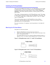
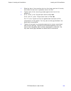
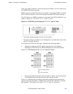
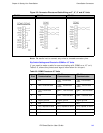
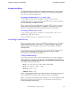
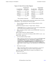
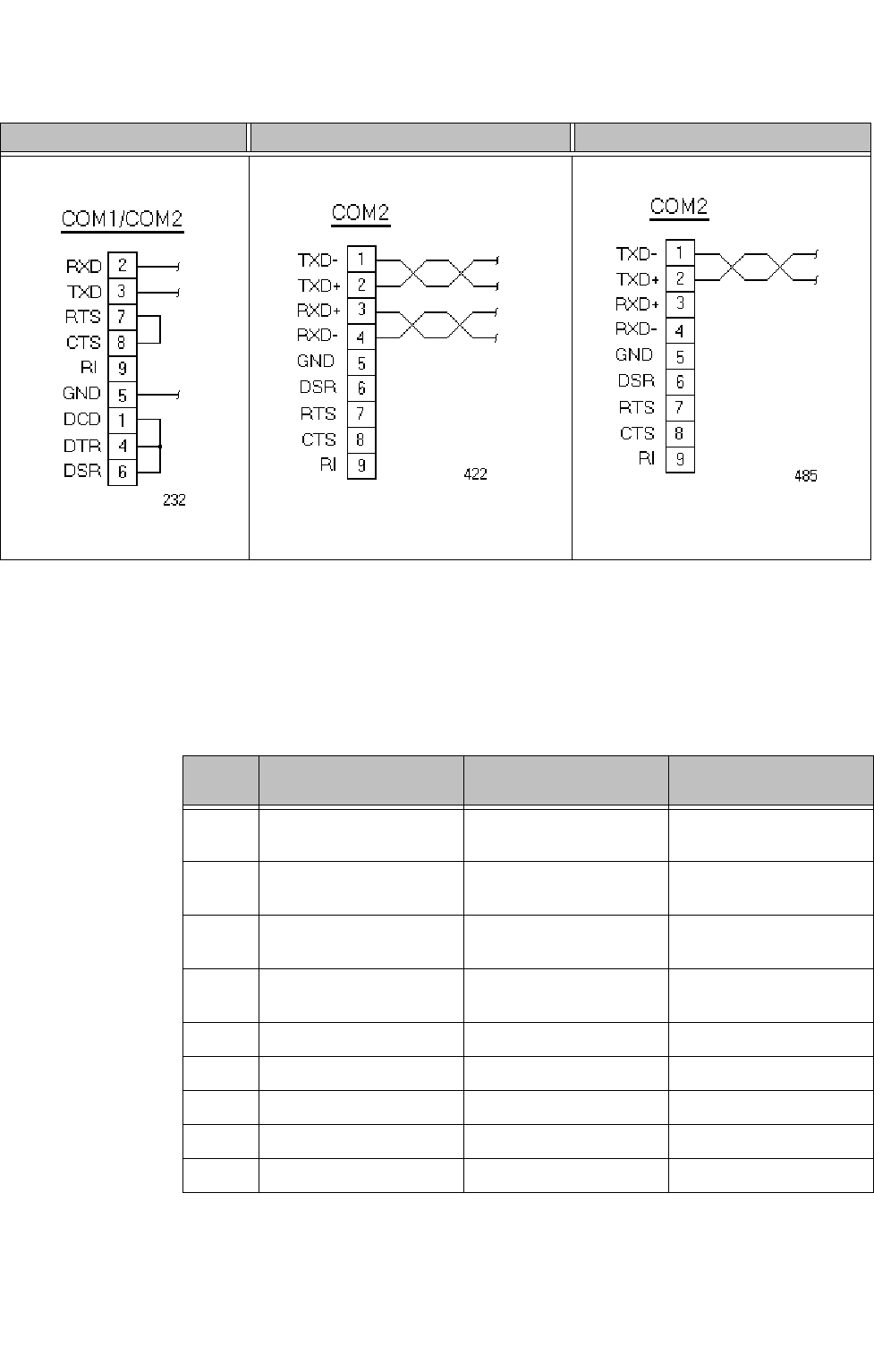
Figure 3-3: Connector Pinouts and Cable Wiring on 5”, 6”, 8” and 10” Units
Note: Be careful not to connect any wires to unused connector pins.
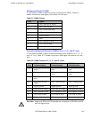
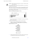
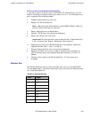
Dip Switch Settings and Pinouts for COM2 on 15” Units
If you need to make a cable for communicating with COM2 on a 15” unit,
Table 3-3, shows the pinouts and signal information for this port.
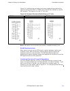
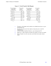
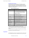
Table 3-3: COM2 Pinouts on 15” Units
RS-232 RS-422 RS-485
Pin#
RS-232
Communication
RS-422
Communication
RS-485
Communication
1 N/C TXD-, transmitted
data -
TXD-, transmitted
data -
2 RXD, received data TXD+, transmitted
data +
TXD+, transmitted
data +
3 TXD, transmitted
data
RXD+, received data
+
RXD+, received data
+
4N/C RXD-, received data
-
RXD-, received data
-
5 Signal ground Signal ground Signal ground
6 N/C N/C N/C
7 RTS, request to send RTS, request to send RTS, request to send
8 CTS, clear to send CTS, clear to send CTS, clear to send
9 N/C N/C N/C