1 • General Information Model 3201 G.SHDSL Integrated Access Device User Guide
14 Front Panel Status LEDs
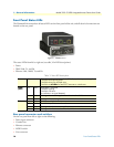
Front Panel Status LEDs
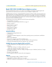
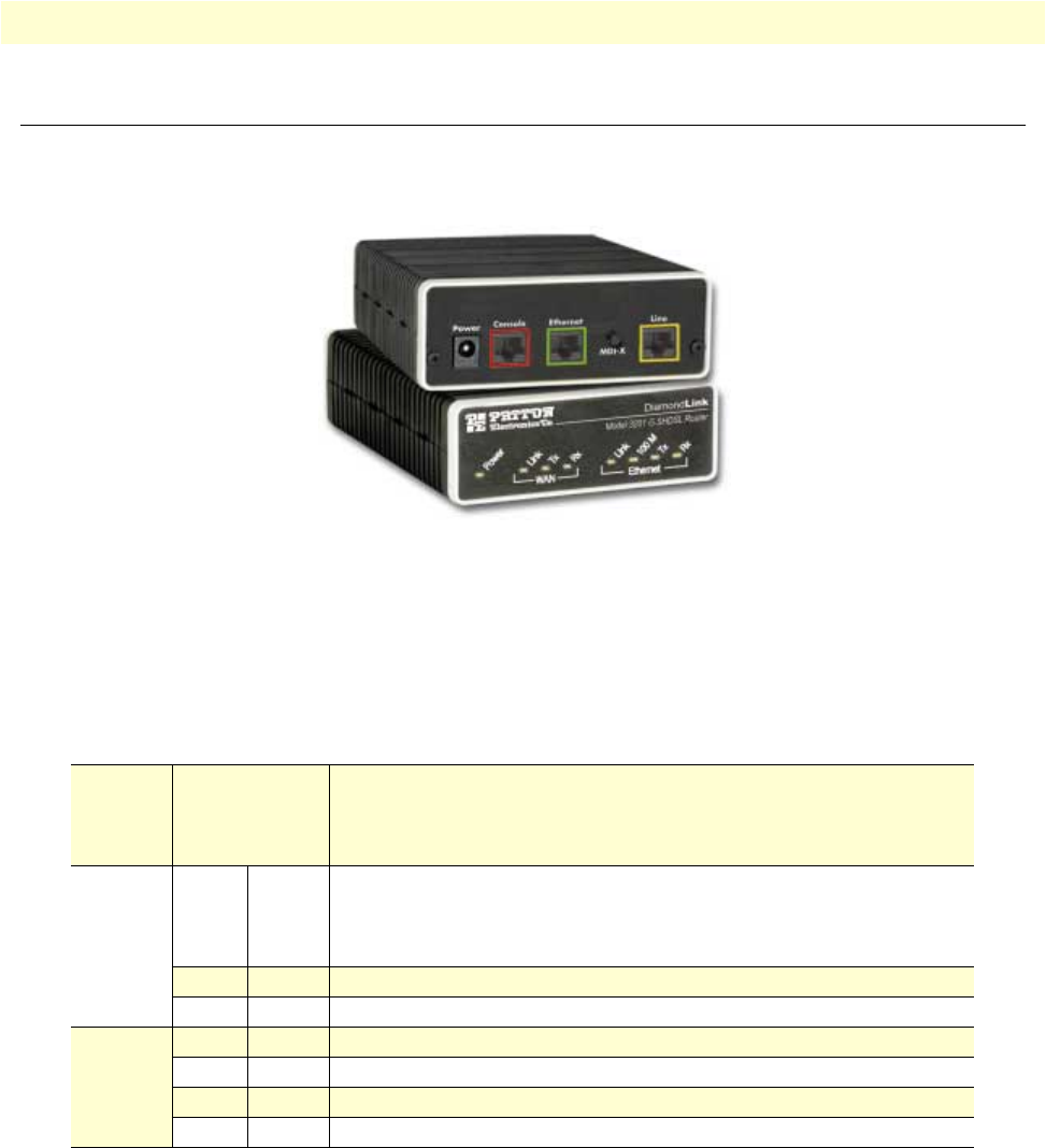
The DiamondLink routers have all status LEDs on the front panel of the unit, and all electrical connections are
located on the rear panel.
Figure 1. Model 3201
The status LEDs from left to right are (see table 3 for LED descriptions):
• Power
• WAN Link, Tx, and Rx
• Ethernet Link, 100M, Tx, and Rx
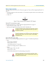
Rear panel connectors and switches
On the rear panel from left to right are the following:
• Power input connector
• Console Port
• Ethernet connector
• MDI-X switch
• Line connector
Table 3. Status LED descriptions
Power Yellow
ON
indicates that power is applied.
Off
indicates that no power is applied.
2 Hz flash
occurs during POST
1 Hz flash
occurs for non-fatal error.
8 Hz flash
on all LEDs for fatal POST outcome or critical error.
WAN
(DSL)
Link Yellow
Solid yellow:
connected
2 Hz flash:
training
8 Hz flash:
DSL error
No indication:
no signal detected.
TX Yellow
Flashing:
when transmitting data from the unit to the WAN.
RX Yellow
Flashing:
when receiving data from the WAN to the unit.
Ethernet Link Yellow
On:
Ethernet is linked.
100M Yellow
On:
100 Mbps Ethernet is selected.
TX Yellow
Flashing:
when data is transmitted from the unit to the LAN.
RX Yellow
Flashing:
when data is received from the LAN.


