


GTX
PAGE 12
CENTURY SERIES
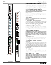
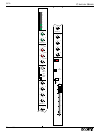
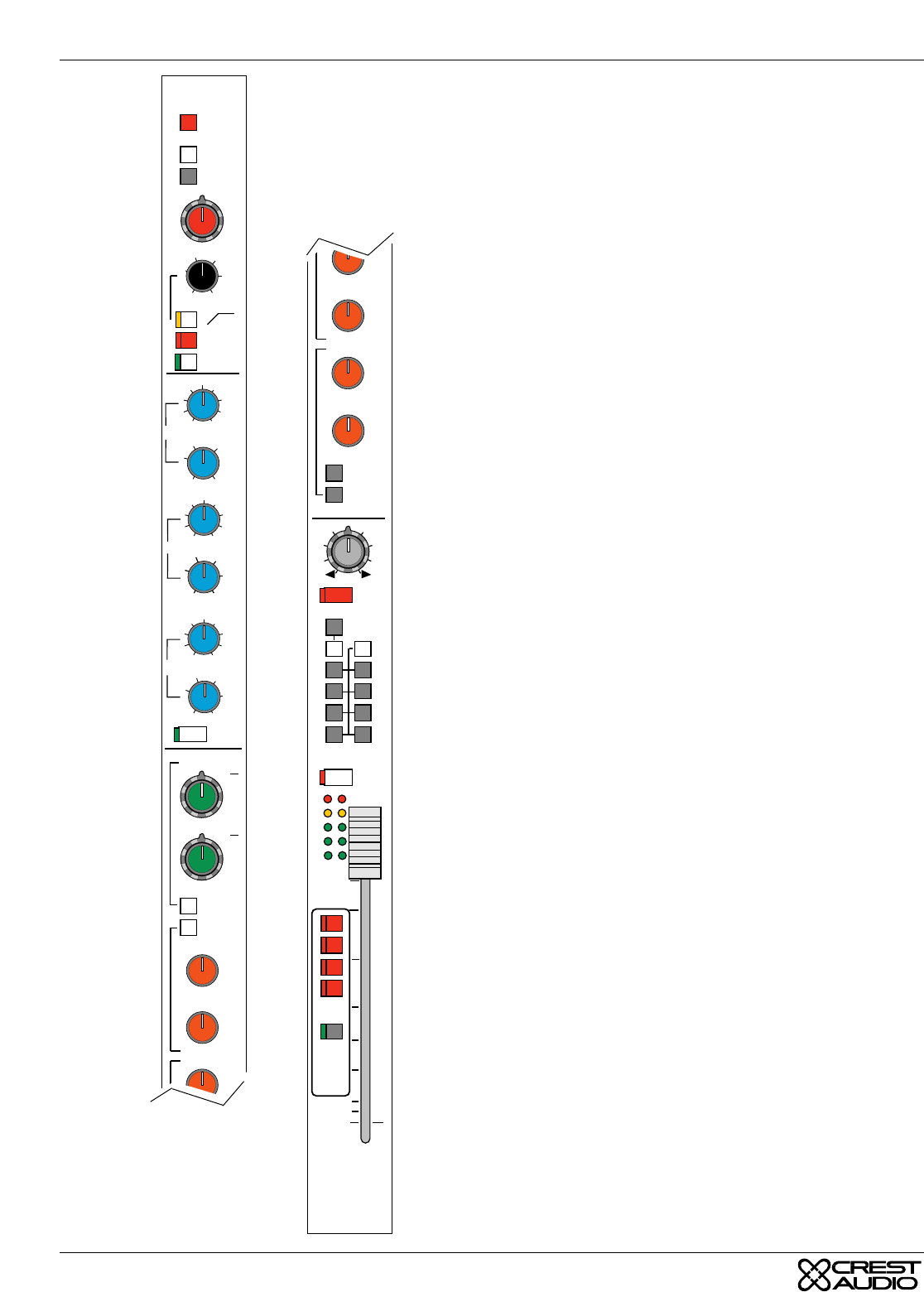
GTx Stereo Input Module
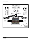
The GTx Stereo Input module is essentially two GTx Input
modules packaged to fit into a one-module space. This mod-
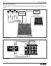
ule is very useful for accepting remote feeds, effects outputs
and other signals that require stereo handling.
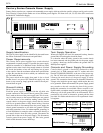
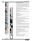
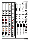
48V Phantom Power Switch
Applies 48 Volts DC to pins 2 & 3 of the both L and R XLR
inputs, for microphones requiring phantom power.
LINE Switch
Switches between the balanced XLR Microphone Input con-
nector and the balanced Line Input 1/4" TRS connector for
both L and R channels.
PAD Switch
Introduces a -20 dB attenuation to the mic input signal for
both L and R XLR inputs.
L GAIN & R GAIN Controls
These concentric controls adjust input gain for proper signal
level for both Left and Right inputs. Maximum gain is 70 dB.
Inner knob is for L GAIN, outer knob is for R GAIN.
Adjustable High Pass Filter
For both Left and Right inputs, reduces all low frequency
content at a -12db per octave rate adjustable from 20 to 400
Hz (-3dB point). Yellow LED illuminates when switch is
down.
Polarity Reverse Switch
For both input channels, inverts the polarity of both the
microphone and line inputs. An internal jumper selects
between Left channel only (default) or both Left & Right
channels. When this switch is pushed, an associated LED
lights.
INSERT Switch
Switches signal processor in and out of L and R signal paths.
Associated green LED is illuminated when switch is down.
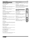
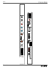
Three-Band Sweep Equalizer
Controls
The equalization controls in this module act upon both L and
R stereo channels at once. All three EQ bands are set up as
sweep EQ’s: the upper knob controls the gain or cut (15 dB);
while the lower knob controls the center frequency adjusted
by the inner knob. Center frequencies are indicated around
the lower knob.
EQ IN Switch
Inserts the EQ section into both L and R input channel sig-
nals at once. An associated green LED illuminates when the
switch is down.
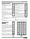
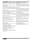
AUX Level 1&2 / 3&4
Adjusts signal level sent to respective Aux buses. The signal
source for this mix may be selected pre or post fader by an
associated switch. The left channel is sent to the odd-num-
bered Auxes, and the right channel is sent to the even-num-
bered Auxes.
PRE
PRE
STEREO
PRE
5
6
7
8
AUX SENDS
7
8
9
5
2
0
1
3
46
10
7
8
9
5
2
0
1
3
46
10
7
8
9
5
2
0
1
3
46
10
7
8
9
5
2
0
1
3
46
10
Ø
HPF
EQ IN
GAIN
40
30
20
50
70
40
20
80
150
300
400
PAD
LINE
+48V
INSERT
BAL
STEREO
—
1
2
3
4
7
8
9
5
2
0
1
3
46
10
7
8
9
5
2
0
1
3
46
10
HF
MF
250
300
400
1
8K
16 16
88
–O+
LF
100
40
150
300
6
1K
16 16
88
–O+
16 16
88
–O+
4K 16K
6K
12K
8K
PRE
PRE
STEREO
PRE
MUTE
PFL
SCENE
MUTE
SELECT
A - D
5
6
7
8
AUX SENDS
SAFE
7
8
9
5
2
0
1
3
46
10
7
8
9
5
2
0
1
3
46
10
7
8
9
5
2
0
1
3
46
10
7
8
9
5
2
0
1
3
46
10
LR
1
3
5
7
M
P
A
N
2
4
6
8
PK
+8
0
-6
SIG
10
0
5
10
20
30
5
15
BAL
WIDTH
3
4
7
8
9
2
0
1
3
10
7
8
9
5
2
0
1
3
46
10