


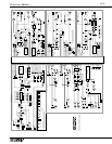


APPENDIX B
GTX
CENTURY SERIES
below the dialed-in frequency. A peak setting would be used to
boost or cut the specific dialed-in frequency.
Line Input Jack
This is a balanced, high impedance input which is designed to
accept both balanced and unbalanced line level inputs. To
select this input source, press the front panel LINE switch. See
the Connections and Conventions section for specific informa-
tion on plug polarity and signal assignments.
Line Switch
This switch, when pressed, selects the balanced Line Input as
opposed to the default balanced XLR Mic input.
Local Monitor Level Control
This control adjusts the level of the signal to the Local Monitor
Outputs on the back of the Master Section. Note that the DIM
switch can be used to introduce a -12 dB attenuation to the
local monitor.
Matrix AFL
See SOLO
Matrix Level Control
These controls adjust the amount of group, L, R or Mono sig-
nal fed to the respective matrix.
Matrix Master Control
These controls adjust the final signal level for the associated
matrix output.
Matrix Post Switch
This button switches the group, L, R or Mono matrix send
between pre and post fader. Up position is pre.
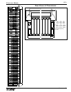
Meter Bridge
The GTx 52 and 64-frame consoles include 21 mechanical
moving-magnet type indicators (44 frame: 13 meters) which
show the output levels. These indicators are VU-type and are
calibrated during manufacturing to 0 = +4dBu, 1.23V RMS
1kHz. The VU-type characteristic averages the signal level
over short time periods (about 300mSec) so that the ‘beat’ is
visible. Short duration peaks (snare drum and other signals
with similar transient peaks) are under-indicated. Meters are
illuminated by amber LED's which do not require attention or
adjustment.
When faders are set a ‘0’ calibration positions, then the opti-
mum signal to noise and overload margin conditions are
obtained. In this situation, signal peaks up to +3 are usually
undistorted. The recommended normal range is between -10
and 0; operation with channel and output levels below -10 is
not recommended - headroom is wasted at the expense of sig-
nal-to-noise ratio. The solo L - R meter pair shows the PFL or
AFL level of the selected source. When no PFL or AFL is
selected, the headphone and monitor output is the main stereo
output. The solo meter is inactive when no PFL or AFL is
selected. For GTx Level Meter calibration information, consult
the GTx Service Manual or your Crest Audio dealer/service
center. (The range of meter adjustment is approximately +1 /-
1dB.)
Mono Bus Assign Switch
Assigns signal directly to the Mono (Center) bus. This signal is
unaffected by the position of the Pan Control, unless L-C-R
panning is enabled. (See BUS ASSIGNMENT for more L-C-R
information). This is useful when it is necessary to add input
signal to the Mono mix without going through the Stereo sec-
tion of the mixer. (An example would be a center vocal cluster
configuration). In addition to the many mono output uses, this
output could be used as an additional send.
Mute Switch
Turns off all send/output functions (except insert send) of the
associated module including those being used as monitors.
This switch does not affect the PFL switch or the LED indica-
tors, enabling monitoring of input channel activity regardless
of mute switch position. The mute LED illuminates when the
channel is muted, either from the local mute switch or from
any activated mute group. When muting a group, the group
meter (on the meter bridge) level will reflect the muting. Note:
the Mute switch may not affect pre signals, depending on inter-
nal jumper settings. Refer to User Options.
Oscillator/Pink In Connector
This connector accepts a balanced or unbalanced signal from
an oscillator or pink noise generator. This signal is assignable
via the talkback assignment switches. Plugging into this jack
disables the internal 1kHz oscillator.
PAD Switch
This -15dB pad (-20dB on Stereo Input module) attenuates the
signal presented to the first stage of the input module. It is
important to note that the Pad Switch acts only upon the bal-
anced XLR input signal; it has no effect upon the 1/4" input
signal. The input GAIN control should be positioned some-
where within its center 80% of travel. In the event that the
Gain control is set in its lower 10% of travel, and the Peak
LED is indicating more than an occasional short illumination,
the PAD Switch should be pressed and the Gain re-adjusted as
above. In the case where the GAIN control is set to its upper
range of travel (3 o’clock position or above) with the PAD
switch pressed, the Gain Control should initially be lowered
and the PAD switch released. The gain should then be
increased and adjusted as above.
Pan Control
Pan Control is a dual device having two functions. Main Mix
Pan operates with Left/Right/Mono assigns. When LCR is
selected, then true LCR panning is provided. Otherwise, L-R
panning is provided. Group Pan operates with the 1-8 group
assigns. When PAN is selected, the odd-even assign panning is
provided.
With LEFT, RIGHT, and MONO assign switches down, and
LCR switch up, LEFT and RIGHT assign signals are propor-
tionally varied by the PAN control, with LEFT and RIGHT
signals being equal in level when PAN is in the center. The
MONO assign signal is unaffected by the PAN control.
With LEFT, RIGHT, and MONO assign switches down and
the LCR switch down, the LEFT and RIGHT assign signals
decrease in level as the PAN control is rotated to its center
position. The PAN control also governs the post fader MONO