


GTX
CENTURY SERIES
APPENDIX B
Glossary
100mm Fader
See
Fader
48 Volt Phantom Power
This switch turns on the +48V DC used to power some micro-
phones. Always operate the 48V Phantom Power switch with
the input channel muted. See XLR Microphone Input for more
information.
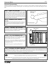
5-Segment LED Array (Input Meter)
This LED array (located next to each input module fader) pro-
vides visual monitoring of the input module signal, post EQ,
pre fader. (On the GTx Stereo Input module, there are two 5-
segment LED arrays.) There are three green LED’s (SIGnal
present, -6, 0) one yellow LED (+8) and one red LED (PK
‘peak’ LED). Under normal operation with proper gain setup,
the LED array should indicate a level between -6 and +8.
When monitoring drum or percussion-type signals, occasional
illumination of the red PK LED is generally acceptable.
In encountering distortion or feedback, this array is handy
when attempting to isolate the source of any problems that may
exist. If the module’s GAIN pot is turned all the way down,
and distortion is still present (indicated by steadily lit red PK
LED), check to see if the PAD switch is pushed down.
Channels which are feeding back show a higher and steadier
meter level. Peak LED on all the time = an overloaded chan-
nel. Use the PAD switch when a gain pot is already at mini-
mum.
2-Segment LED Signal Indicators
This LED array provides simple in-module visual monitoring
of the Group, Matrix, and Master module signals. The green
LED is the ‘signal present’ indicator, and the red LED is the
‘peak’ LED. The ‘peak’ LED also doubles as a PFL-on indica-
tor. Signal is sampled pre and post fader to reveal any source
of overload.
Adjustable Hi Pass Filter
This input module control (actually two controls: a rotary pot
to adjust frequency, and the on/off HPF switch) permits the
exclusion of all signals below the dialed-in frequency. An
associated yellow LED is illuminated when the HPF switch is
down. the rotary pot adjusts the Hi Pass frequency from 20 to
400 Hz, with a slope/roll off of 12 dB per octave. This is useful
in dealing with unwanted ‘rumble’, often encountered in live
mixing as a result of microphone movement or bumping. On
the GTx Stereo Input module, the Hi Pass Filter acts upon both
channels.
AFL (After-Fader-Listen)
See SOLO
Aux Meters
Located on the GTx 64-frame and 52 frame meter bridges,
these VU-type meters indicate the 8 Aux output levels. On the
GTx 44 frame model, Aux monitoring is accomplished via the
Solo (AFL) circuit.
Auxiliary Pre/Post Switches
Configured in three groups (1-4, 5-6, 7-8) these switches per-
mit the associated Aux sends to be either pre-fader or post-
fader. A typical application would be to use one group of aux
sends pre-fader as monitor sends, and to use another group
post-fader as effects sends. Note that if the Aux 8 Direct switch
is pushed, the Aux 8 send will be a pre-fader direct out send,
regardless of the Aux 7&8 Pre/Post switch selection. Pre-fader
aux sends may be affected by the MUTE switch. Refer to User
Options.
Auxiliary 8 Direct Switch
This switch disconnects the Aux 8 level control from the Aux
8 mix bus and instead is used to control the Direct Output of
the channel. Normally the Direct Out jack is post-fader. When
the Aux 8 Direct switch is pressed, the Aux 8 level control
assumes output control of the direct out signal, and the Aux 8
control is fed pre-fader.
Auxiliary Bus 1-8
The Aux bus carries signal from the Aux Send controls to the
Aux outputs on the rear panel of the Master Section. A typical
setup would entail using the Aux 1-4 sends for monitor mixes
while Aux 5-8 are used for effect sends. If a separate monitor
mixer were being used, Auxes 1-4 could be used for additional
effect sends. Effects can be returned via the EFX Return sec-
tion of the group modules or through spare input modules.
Auxiliary Master Mute Switch
Enables the four Aux Send Mutes. Associated LED indicates
selection.
Auxiliary Mute Switches
The Master Section of the GTx consoles has mute switches for
each Aux output. When pressed, this switch mutes the corre-
sponding Aux Send Master. When the mute is engaged no sig-
nal leaves the associated Aux out jack and a red LED illumi-
nates to the left of the switch. These mute switches are active
only if the Aux Mute Master switch on the Master module is
pressed.
Auxiliary Send Controls
The GTx console employs eight discrete Aux Sends per input
channel which send signal to the Aux bus. These sends are
controlled via the eight level controls on each input module.
Aux Sends 1-4 (orange colored, dual concentric) are typically
used for monitor sends. Aux Sends 5-8 (green) are typically
used for effect sends. Each effect return section has Aux 1-4
Send controls, which could be used for adding effect return
signal to the monitor mix.
Balanced Insert Return Jacks (Group
Module)
See GROUP INSERT SEND/BALANCED INSERT
RETURN JACKS.
Balanced Insert Return Jacks (Input
Module)
See INSERT SEND/BALANCED INSERT RETURN JACKS.
Blend to L/R Mixes
Permits ‘blending’ of the Left & Right signals to Auxes 1&2
and/or Auxes 3&4. Two controls are provided: Rotary level
control, & two push buttons to select Auxes 1&2 and/or Auxes
3&4. The Blend feature is useful when it is necessary to send
the Left & Right bus signals to monitor mixes or remote feeds.