


APPENDIX B
GTX
CENTURY SERIES
Fader Reverse Switch
This switch swaps roles between the Effect Return Level pot
and the Group Fader. When pressed, this switch causes the
Effect Return Level to be controlled by the group fader, and
the group level to be controlled by the Effect Return Level pot.
If you want fader control when setting effect returns, this
switch is particularly helpful. A red LED indicator is provided
to the left of the switch and illuminates when the switch is
pressed (reverse mode).
Gain Control
This knob (-20 to 70 dB) adjusts input gain circuitry for proper
electrical operation with any input signal level. Adjust this
control by monitoring the input meter LED’s for bright intensi-
ty, with peak (red) LED flashing only occasionally when the
loudest program material is present. When using this method
for adjustment of the Gain Control, normal signal level should
be adjusted to show a level between -6 and +8. Constant distor-
tion on an input channel could mean that the input channel is
being overdriven. Check for improper input gain adjustment
first. (When a PFL switch is pressed on an input channel, this
signal can also be observed on the Left/Right Solo monitor
meters within the GTx meter bridge.)
Ground
Console chassis and audio ground are connected together. The
console power supply includes an external link that connects
console ground to AC power ground. This link is provided for
user selection when optimising system ground requirements.
Group Assignment
(See Bus Assignment)
Group Insert Send/Balanced Insert
Return Jacks (Group Module)
These jacks allow you to access a point in the group module’s
electrical circuit for inserting an external signal processor. The
output level of this connector is designed to drive the inputs of
most external signal processing equipment and to accept the
resulting output signal. When properly wired TRS plugs are
inserted in these jacks, the patched devices are inserted into the
signal path immediately pre-fader. See the Connections and
Conventions section in the front of the manual for specific
information on plug polarity and signal assignments.
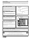
Group Meters 1-8
Located within the meter bridge, these VU-type meters moni-
tor the post-fader output of the groups. Similar meters on the
Master Section monitor Left, Center (Mono) and Right out-
puts. 0 Level = +4dBu output level.
Headphone Jacks
Located at the top of the master section and under the right
side of the arm rest, these jacks provide a stereo headphone
level output of the Left, Center (Mono), and Right outputs.
When L-C-R panning is enabled, the Center Bus will not be
audible in the headphones; the Center Bus must be PFL'd to
monitor it audibly.
Headphone Level Control
This control (marked PHONES and located in the upper right
Master section) adjusts the level of the signal fed to the two
headphone jacks; one of these jacks is located next to the
PHONES control, and another is just below the armrest on the
far right side.
HF Peak/Shelve Switch
This switch is used for switching the high frequency EQ con-
trol between the normal shelving setting to a peak setting. A
shelving setting would be used to boost or cut all frequencies
above the dialed-in frequency. A peak setting would be used to
boost or cut the specific dialed-in frequency.
High Pass Filter (Adjustable)
See ADJUSTABLE HIGH PASS FILTER
Insert Send/Balanced Insert Return
Jacks (Input Module)
These jacks allow you to access a point in the channel’s elec-
trical circuit for inserting an external signal processor. The out-
put level of the Insert Send jack is designed to drive the inputs
of most external signal processing equipment and to accept the
resulting output signal. When a properly wired TRS plug is
inserted in these jacks and the Insert switch is down, the input
signal path is broken after the gain stage and the high pass fil-
ter. The Balanced Insert Return jack feeds the return signal to a
point just before the EQ section. See the Connections and
Conventions section in the front of the manual for specific
information on plug polarity and signal assignments. (With the
Insert switch down, the insert return jack may be used as a line
level input to the channel that bypasses the mic preamp,
mic/line switch, pad, gain control, and hi pass filter.)
Insert Switch w/LED
This switch, located on the GTX Input (and GTX Stereo Input)
modules, introduces into the signal path any processing that is
patched into the Insert Send and Balanced Insert Return jacks
on the rear panel. An associated green LED is illuminated
when the Insert switch is down.
Internal Oscillator
The GTx master section has a 1 kHz internal oscillator. This
oscillator can be used as signal source to run tests, diagnostics
or calibrations. The oscillator can be assigned to all Groups,
Auxes and Matrices via the Talkback assignment switches.
Lamp Dim Control
This control adjusts the brightness of whatever lighting devices
are plugged into the XLR sockets on the meter bridge.
(Standard 12V DC power is provided on pins 2 & 3).
L-C-R Switch
Provides true L-C-R pan to the main mix outputs. When this
switch is released, the pan operates on L&R in the normal
fashion. See also PAN CONTROL.
Left Meter
Located on the GTx meter bridge, this VU-type meter indicates
the Left output level, post fader.
LF Peak/Shelve Switch
This switch is used for switching the low frequency EQ control
between the normal shelving setting and a peak setting. A
shelving setting would be used to boost or cut all frequencies