


GTX
APPENDIX A
CENTURY SERIES
General Specifications -
GTx Console
The following are the technical specifications for the Century
GTx console.
Frequency Response
+0.0, -0.5dB, 20Hz to 20 kHz (referenced to 1kHz)
Total Harmonic Distortion
Mic input to Group output
20Hz to 20 kHz at +15dBu <0.01%
Noise (22Hz to 22kHz)
Mic EIN -129 dBu
Mix bus Output Noise (20 ch routed) - 80 dBu
Aux bus Output Noise (20 ch routed) - 80 dBu
Crosstalk (Measured at 1kHz)
Channel Mute >102 dB
Channel Fader Attenuation > 96 dB
Channel Routing > 85 dB
Channel Aux Send Attenuation > 93 dB
Input/Output Impedances
Mic Input 4kΩ balanced
Line Input >10kΩ balanced
Outputs 140Ω balanced
Input/Output Levels (0VU = +4 dBu, 1.23V RMS)
Mic Input Sensitivity + 4 to -62 dBu
Line Input Sensitivity + 12 to -38 dBu
Input Insertion Point Level + 4 dBu
Output Insertion Point Level - 2 dBu
Nominal Output Level + 4 dBu
Maximum Balanced Output Level +28 dBu
Configurations
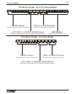
Century GTx consoles are available in the following eight-bus
configurations:
32 inputs (44 Frame)
40 inputs (52 Frame)
52 inputs (64 Frame)
All Century GTx consoles are available with stereo input
modules and additional matrix modules.
Architect’s & Engineer’s
Specifications
The following text should be used when specifying a Century
GTx in a bid or proposal.
The GTx live sound console shall be constructed in a modular fashion and be housed
in a steel frame of (44, 52, 64) module positions. The console shall be usable in
either a 'tabletop' set up or with optional stands. A standard output module configu-
ration will occupy 12 module positions including a standard 2 channel output matrix
system. The console shall be black with white labeling and utilize XLR lighting
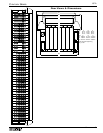
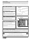
device connectors with dimmer system. A meter bridge shall be included that moni-
tors console signals using mechanical meters with solid state illumination. Signals to
be monitored include Left output, Right output, Mono (Center) output, Stereo PFL
signal and 8 group output signals. On 52 and 64 module position frames, 8 auxiliary
output meters are also to be provided. The console shall have a pair of XLR talkback
mic and headphone jack connectors, with one set being located beneath the far right
side of the armrest and a second pair on the top panel of the console. The GTx live
sound console shall feature a defeatable Left-Center-Right (LCR) panning system.
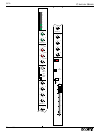
On each input channel: All microphone inputs shall be electronically balanced and
accessed via 3-pin XLR connectors and have an EIN of -129 dBm. All input channel
line inputs shall be electronically balanced and accessed via 1/4" TRS jacks. Input
module insert and return points shall be via individual 1/4" jacks and controlled by a
front panel switch with LED. Additional input controls include: a +48 volt phantom
power switch, a -15 dB pad switch (-20 dB for stereo input channels), adjustable
high pass filter control (20-400Hz) with on switch and LED, a polarity reverse
switch with LED, and 4-band sweep EQ (LF- 40-800Hz, LMF- 100Hz-2kHz, HMF-
400Hz-8kHz, HF- 1.5k-20kHz) with peak/shelve switches on the high and low EQ
bands, switchable bandwidth on low-mid and high-mid bands, and an EQ In switch
with LED. Each input channel shall also have a FET controlled (10 millisecond
ramp) mute switch with LED, affecting all assigned outputs including auxiliary
sends. Assignment switching is provided to the following output sections:
Left/Right, Mono, Subgroup 1, Subgroup 2, Subgroup 3, Subgroup 4, Subgroup 5,
Subgroup 6, Subgroup 7 and Subgroup 8. An LCR switch reconfigures the
Left/Right and Mono assignment system to a true Left/Center/Right mix system. A
Pan On switch allows conventional panning between any odd and even subgroup
assignment regardless of the position of the LCR configuration switch. A 5-segment
signal level LED indicator is provided to monitor signal levels, and a multiple sam-
ple point peak LED is provided to monitor potential overload situations. Input mod-
ules also include a PFL switch with LED indicator, 4 scene mute preset switches,
scene mute safe switch with LED, and a 100mm long throw fader. Each input chan-
nel shall have eight auxiliary send level controls. The aux send section shall include
three pre/post fader switches: one for auxes 1-4, one for 5&6, and one for 7&8. The
aux sends shall be internally selectable pre or post EQ and pre or post mute. There
shall be an Aux 8 direct switch that shall allow the Aux 8 rotary knob to directly
control the output of the 1/4" direct output connector. Optional stereo input modules
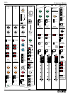
will be available. The console shall be configured in an eight bus arrangement. The
effect return section of each group module shall have a gain control, a two-band
fixed EQ, sub-group assignment switches, L/R and Mono assignment switches with
an LCR configuration switch, aux send level controls for Auxes 1 through 4 with 1-2
switchable to 5-6, and 3-4 switchable to 7-8, a pan control, a level control, a dynam-
ic signal present LED and peak LED, and a PFL switch. 4 scene mute switches (A-
D) with scene mute safe switch with LED will be available on each return section.
The group mix section of the module shall have a pan control, a FET controlled (10
millisecond ramp) mute switch with LED, assignment switches for Left/Right and
Mono with an LCR configuration switch. Each group mix section will have balanced
(XLR) group insert connections. There will be a send level control for two Matrix
mixes (A & B) on each group module with source selection matrix post fader switch.
It shall also have a fader reverse switch with LED that allows the group fader to con-
trol the level of the modules effect return. A PFL switch, dynamic signal present
LED and peak LED, and a 100mm long throw fader shall also be provided on the
group module. The master section shall have the following features: eight aux master
controls with associated AFL switches and eight aux scene mute switches with
LED's, a 100mm long throw fader for each of the Left, Right, and Mono (Center)
master outputs, balanced (XLR) insert connections for Left, Right, and Mono
(Center) master outputs, an assignable comprehensive talkback system, monitor con-
trol (with balanced XLR output), stereo program input section with Stereo EQ, lamp
dimming control, and four+two aux scene mute master switch section, each with
LED. Two master matrix output sections include level control, Mute switch with
LED, AFL monitor switch and peak and signal present LED indicators. The two
Matrix output signals are to be derived from the consoles group output signals, left,
right, and mono output signals. Additional matrix output modules may be installed in
the console frame if unused space is available. The power supply shall be housed in
a 14 ga. steel chassis that shall occupy two 19" rack spaces. The power supply shall
have the ability to be daisy-chained to additional power supplies to provide a fail-
safe operating environment. Connection of two or more power supplies shall not
require additional interface hardware other than interface cable. The live sound con-
sole shall be: the Crest Audio Century GTx.