


APPENDIX B
GTX
CENTURY SERIES
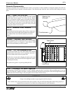
Bus Assignment Switches
Wherever these switches occur, they connect signals to any or
all of the following buses: Group buses, even/odd Group
buses, Left bus, Center (Mono) bus, and Right bus. The fol-
lowing list shows the various Bus Assignment switches and
their effect upon bus assignment:
M - Signal is sent to the Center (Mono) Bus.
LR - Signal is sent to the Left and Right Buses, via pan.
LCR - Configures Left/Right and Center/Mono assignments for L-C-R pan-
ning. To enable L-C-R panning, L-R and Mono assign switches must be down.
PAN Switch / Group Assign Switches (1-8) - With PAN switch down, the
PAN control varies the level of the group assignments with odd numbered
groups on the left and even numbered groups on the right. With PAN switch
up, groups can be individually selected and are unaffected by the PAN control.
Group assign switches route signals to the Group buses.
It is a common practice to assign all effect return channels to a
group module. This enables the overall amount of effect signal
to be controlled from a single fader location. It is then possible
to turn off the effects with this group fader or group mute
switch or to vary the amount of overall effect return in refer-
ence to the dry original signals, using the group fader control.
CENTER Meter
Located on the meter bridge, this VU-type meter indicates sig-
nal level sent to the Center (Mono) bus.
DC Power Indicators
Each Century Series console uses a variety of electrical volt-
ages which are fed to the console from the power supply. The
status of each operating voltage (+20, -20, +48, +24) is indicat-
ed by four LED’s on the master module. If the console ever
behaves abnormally, first check these LED’s to make sure that
the power supply is providing the proper voltages.
Dim Switch
This GTx Master Section switch produces a -12dB attenuation
in signal to the local monitor. This feature is useful for tempo-
rary lowering of local monitor levels without actually adjusting
any pots or faders.
Direct Out Jack
Each input module has an unbalanced 1/4" direct out jack. The
output from this jack is post-fader unless the AUXILIARY 8
DIRECT switch is pressed. When this switch is down the out-
put is controlled by the Aux 8 pot. See AUXILIARY 8
DIRECT SWITCH for more information.
Effect Return EQ
Located in the GTx Master section, each effect return section
has a two-band fixed EQ. These High and Low frequency con-
trols are centered at 10kHz and 80Hz respectively. Center posi-
tion is flat.
Effect Return Gain
Located in the GTx Master section, this control adjusts the
gain on the signal returning from the effect. Use the effect
return signal present and peak LED’s to set the gain properly.
Effect Return Subgroup Assignments
These switches assign the corresponding effect return to any or
all subgroups. See BUS ASSIGNMENT SWITCHES for more
information.
EQ In Switch
This GTx input module (and stereo input module) switch,
when pressed, inserts the EQ section into the signal path and
illuminates a green LED to the left of the switch. With the
switch in the up position, the input signal bypasses the EQ sec-
tion and continues unmodified.
EQ Sections
These controls are used to modify the tonal quality of an audio
signal. Within the input modules, the EQ section will affect the
signal only if the EQ IN button is pressed.
The GTx standard input module has a four-band sweep EQ
section, including concentric adjustment of frequency and
boost/cut, selectable peak/shelving EQ on the high and low fre-
quency bands, and selectable Q on the two middle frequency
bands, switchable between .8 (Q switch up) and 1.8 (Q switch
down).
The GTx stereo input module has a three-band sweep EQ sec-
tion, with individual controls within each band for adjustment
of frequency and boost/cut.
The effect return sections, within the group modules, have
two-band EQ sections, with fixed EQ controls.
External Talkback Inputs
Located at the top of the GTx Master section and under the
front right console armrest, the External Talkback Inputs per-
mit connection of talkback microphones to be used with talk-
back functions. Only one microphone should be connected;
using both inputs at once is not recommended. Note: the inter-
nal jumper default for this input is +48V DC!
External Talkback Input Switch
Located in the Talkback Control section (Master Section), this
switch disconnects the two regular talkback microphone inputs
and switches on the external talkback input XLR found on the
rear panel of the GTx master section. Note: the Talkback
Control Button must be on for this switch to function.
External Talkback Output Switch
Located in the Talkback Control section (Master Section), this
switch activates the external talkback output XLR. The signal
fed to the connector is the same signal being sent to the talk-
back assignments. Note: the Talkback Control Button must be
on for this switch to function.
Fader
The fader is used for primary level control of the channel,
except those Aux output sections selected to a pre-fader posi-
tion. (The Insert send level is not affected by the fader posi-
tion.) Optimum noise performance is achieved when the fader
is operated near the 0 fader position, with pad switches and all
gain controls properly set. This does not mean that all channels
should be set at 0. Proper mixing requires varying of at least
some of the faders. The 0 point should be considered a refer-
ence, with all volume changes taking place between the -10
and +10 reference points at normal desired levels. For effect,
faders may be operated below this level, provided no faders
within the group or master section are increased in level to
compensate for the input’s lower fader setting. (See also
FADER REVERSE SWITCH).