


GTX
PAGE 13
CENTURY SERIES
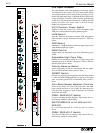
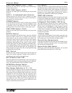
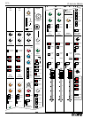
PRE/POST Switch (1&2 / 3&4)
Selects the Aux 1&2 and Aux 3&4 signal sources between post
and pre-fader positions.
PRE/POST Switch (5&6)
Selects the Aux 5&6 signal sources between post and pre-fader
positions.
AUX 5 - 8 Individual Level Controls
Adjusts audio level of a mix for use as a monitor or an effect
send. The signal source for these mixes may be selected pre or
post-fader by an associated switch.
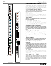
STEREO Switch
AUX 7&8 Individual Level Controls normally send a summed
(L+R) signal to the AUX outputs. When the STEREO switch
is depressed, AUX 7 and 8 become a send ‘left’ and ‘right’
send respectively. This can be used for a stereo effects send.
PRE/POST Switch (7&8)
Selects the Aux 7&8 signal sources between post and pre fader
positions.
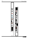
WIDTH Control
When used together with the BAL(ance) control, the WID(th)
control provides a unique way to configure stereo panning.
When turned all the way counter-clockwise, this control con-
ventionally assigns the left signal to the left (odd) channel
assignment, and the right signal to the right (even) channel
assignment. When adjusted to the ‘twelve o’clock’ position,
left and right signals are panned straight up the middle, effec-
tively summing them to mono. When this knob is turned all the
way clockwise, the left and right signals are ‘flip-flopped’, left
being assigned to the right (even) side, and the right side being
assigned to the left (odd) side.
BAL Control
Positions the entire channel image between the left (odd) and
right (even) channel assignment. Together with the WID con-
trol, this gives total control of the stereo image.
MUTE Switch with LED
Mutes the channel and all send functions. This switch does not
affect the PFL switch or the Peak and Signal Present LED indi-
cators. The LED illuminates when the channel is muted.
MONO Bus Assign Switch
Assigns the input signal directly to the Mono bus.
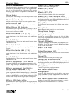
Bus Assign Switches (L/R, 1-8)
Assigns the post Pan signals to mix bus in odd/even-numbered
pairs. Pan controls assignment between these two mix buses
with extreme left pan assigning signal exclusively to the odd-
numbered mix bus and extreme right pan assigning signal
exclusively to the even-numbered mix buses. When the pan is
in its center position, signal is fed equally to the odd (left) and
even (right) mix buses. When used in stereo applications, the
channel signal may be located anywhere within the stereo
image as controlled by the Pan control.
PFL Switch
Samples the channel’s signal pre-fader and allows for monitor-
ing within the master section of the console. This signal is not
affected by the Mute Switch. When depressed, the signal level
can be seen on the Solo meters, and heard via the mixer’s
headphone or local monitor output. When this PFL Switch is
depressed, the channel PFL LED indicator illuminates.
PEAK LED Indicator
Illuminates RED when any of the points monitored come with-
in 3db of the clipping point. Signal is sampled after the input
preamplifier stage, after the EQ section, and after the fader.
5-Segment Dual-Ladder LED Array
This dual LED array monitors the stereo signals pre-fader.
Signal Present LED (green) responds to levels as low as -30
dB and comes to full brightness at -8dB, varying in intensity
according to level. -6dB LED (green), 0dB LED (green), and
+8 dB (yellow) illuminate accordingly. The Peak (red) LED
responds to overloads at three points in the module; pre-EQ,
post-EQ, and post-fader.
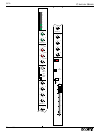
100mm Fader
Used for control of all outputs of the channel except those Aux
output sections selected by switch to a pre-fader position. (The
Insert output level is not affected by the fader position.)
Scene Mute Assignments
Assign the input channel to any of the four Scene Mute groups.
Scene Mute combines with the module’s local Mute button,
and actuates the local Mute LED.
Scene Mute Safe Switch
Disables any selected Scene Mute assignments. An associated
green LED indicates the channel is in a Safe state.