


GTX
PAGE 6
CENTURY SERIES
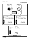
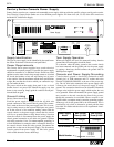
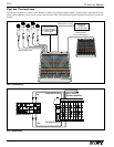
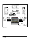
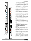
Century Series Console Power Supply
Century Series consoles use a separate rack-mountable power supply which provides the specific voltages used by each console.
Crest Consoles’ Century Series makes use of two different power supplies. All frame sizes (44, 52, 64) of the GTx console use
the Model XCVA06 Power Supply.
Power Supply
C O N S O L E S
+20V
-20V
+48V
+24V
Press to Reset
6A
ON
Designed & manufactured in the USA by:
A division of Crest Audio Inc.
100 Eisenhower Dr.
Paramus, New Jersey 07652 USA
POWER OUT
POWER OUT
RISK OF ELECTRIC SHOCK
DO NOT OPEN
CAUTION
AVIS : RISQUE DE CHOC ÉLECTRIQUE—NE PAS OUVRIR
WARNING TO REDUCE THE RISK OF FIRE OR ELECTRIC SHOCK DO NOT
EXPOSE THIS EQUIPMENT TO RAIN OR MOISTURE.
ATTENTION! POUR ÉVITER LE RISQUE D'INCENDIE OU DE CHOC
ÉLECTRIQUE, NE PLACEZ PAS CET APPAREIL SOUS LA PLUIE OU Á
L'HUMIDITÉ
6
7
2
1
4
5
3
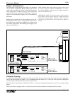
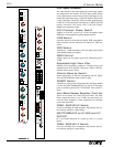
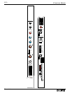
Pin 1 +24V
Pin 2 +20V
Pin 3 Analog
Pin 4 Analog
Pin 5 Digital
Pin 6 +48V
Pin 7 -20V
CONSOLE
GROUND
CHASSIS
GROUND
MAXIMUM AC IN:
XCVA04: 415 WATTS
XCVA06: 825 WATTS
+ 48V @1
+ 24V @6
± 20V @ 6
Model XCVA06
Model XCVA04
± 20V @ 4
+ 24V @4
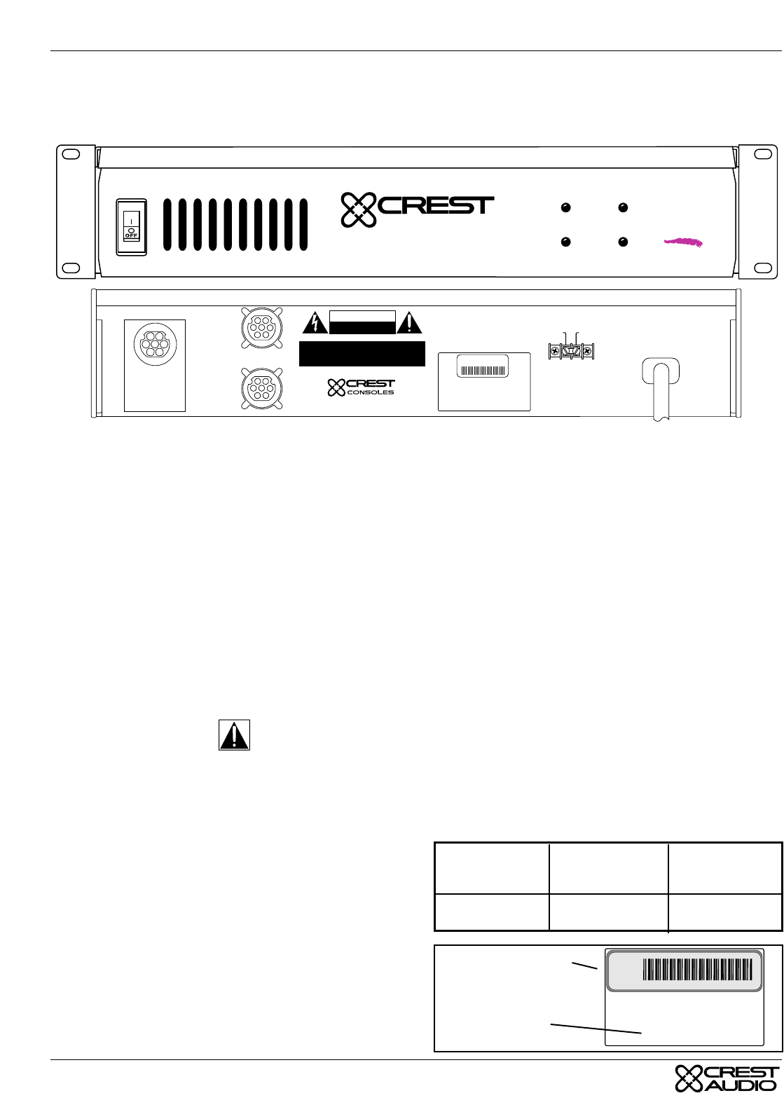
S/N
Supply Identification
The type of power supply can be identified by the model num-
ber shown on the back of the chassis and panel label..
Power Requirements
The Century Series power supplies have certain electrical
requirements to operate properly. If possible the power supply
should be connected to a dedicated circuit. Should any other
appliance on the same circuit draw enough current to overload
the circuit, the breaker or fuse will trip causing loss of power
to the console. Note the maximum current draw specifications
at right. Be sure that the circuit to which you connect the sup-
ply can handle the draw.
The power switch on the supply front panel is also a circuit
breaker, there is no power fuse. Should the supply ever shut
down, or trip at start up, simply push the switch to the off posi-
tion and then on again.
Ground Linking
Safety Considerations -
Each new power supply is shipped with the AC third wire
ground connected to the console chassis ground. The connec-
tion is made at the rear of the power supply unit. This is neces-
sary for safety reasons so that exposed metal parts are ground-
ed. In the event of a live conductor making contact with the
console chassis or the power supply chassis then the current
will flow to ground without a safety hazard arising. Note that
when the console is disconnected from the power supply the
chassis ground connection to AC third wire ground is broken
and safety protection is lost. For uninterruptible grounding, in
a fixed installation for example, make a connection directly to
the console chassis from the safety ground. Disconnect the
ground link on the rear of the power supply. This disconnects
console ground from power supply AC third wire ground
which would otherwise create a hum-loop.
Twin Supply Operation
When twin supplies are in use for automatic back-up, then the
ground links on both supplies should be fitted.
In a situation where the safety ground to the console chassis
has been connected and the ground path via the power supply
is causing a hum-loop, then disconnect the ground links on
BOTH power supplies.
Console and Power Supply Grounding
Console chassis ground is electrically connected to audio
ground, pin 1 of XLR connectors and 1/4" sockets and to the
terminal 'CONSOLE GROUND' at the rear of the power sup-
ply. The AC third wire connection in the power supply cable
connects the metal chassis of the power supply to safety
ground. This connection should never be disturbed. Hazardous
voltages exist inside the power supply which require the case
to be grounded. When rack-mounted, the power supply ground
may transfer to the rack case thru the front fixing screws,
though this connection is not reliable. When a console is con-
figured within a complete sound system the grounding require-
ments may call for the ground link to be disconnected. This is
permissible only when an alternative ground path has been
provided. If in doubt seek the advice of an experienced electri-
cal engineer.
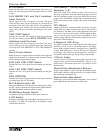
+48V @ 1A
+24V @ 6A
±20V @ 6A
Model
XCVA06
Model XCPS-40
±20V @ 4
+24V @ 4
S/N
Power Supply
Model
XCVA06
Max Current
Draw @ 120V
9 Amps
Max Current
Draw @ 240V
5 Amps
Serial Number Tag
Model Number