


GTX
PAGE 29
CENTURY SERIES
Console Disassembly
Though you shouldn’t have to disassemble the console, it is necessary to remove modules to change the jumper and switch set-
tings associated with the internally selectable options. The following steps detail the tasks involved when taking the console
apart.
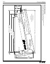
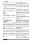
ONE • Open the armrest.
To properly remove one or many modules, the black painted
armrest must first be opened. To do this, the two thumb-
screws (see diagram at right) must be loosened from below.
Once these screws are loose, slide both of them a few inches to
the side (they will only move in one direction). Once the
screws have been moved the armrest will easily roll back
exposing the module screws beneath.
TWO • Remove front module
screw
Once the armrest has been opened, there will be a single screw
at the front edge of the module panel holding each module in
place. Remove the screw from the module(s) you want to
remove.
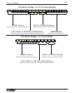
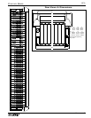
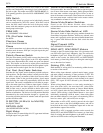
THREE • Remove rear screws
On the back panel of the console there are two screws holding
each module in place (see diagram at right) Remove both
screws from each module you wish to remove.
FOUR • Lift the module(s) out
As you lift the module out of the chassis three wires must be
detached before the module can be completely removed: 2
flat-wires (ribbon cables) and one ground wire.
The flat-wires are removed by flipping the latches on the ends
of the connectors. Once the tabs have been flipped the connec-
tor should pull off easily.
The ground wire (green) is a spade lug which pulls off.
FIVE • Putting it all back together
Re-assembling a Century Series console is as easy as taking it apart, but only if you know where everything goes. If you are
going to be removing a number of modules, consider replacing the first before removing the second. Reversing the above steps
should result in the console being as well put together as it was when it left the factory.
Opening the
Armrest
Thumbscrews
INSERT RETURN
MONITOR A LEFT
BAL OUT
INSERT SEND
EXT TB IN
INSERT RETURN
MONITOR B LEFT
MONITOR B RIGHT
BAL OUT
INSERT SEND
OSC IN
MONITOR A RIGHT
BAL OUT
INSERT SEND
INSERT RETURN
RETURN 1
RETURN 2
EXT TB OUT
BAL OUT
INSERT SEND
INSERT RETURN
BAL INSRT R
T
DIR OUT
INSRT SND
BAL MIC IN
BAL MIC OUT
LIFT
PIN 1
BAL LINE IN
Upper Screw
INSERT RETURN
BAL OUT LEFT
INSERT SEND
INSERT RETURN
BAL OUT RIGHT
INSERT SEND
INSERT RETURN
BAL OUT LEFT
INSERT SEND
INSERT RETURN
BAL OUT RIGHT
INSERT SEND
Lower Screw
Light Bar
IMPORTANT
Group, Left, and Right modules are pre-assigned at the Crest factory
These modules must always be installed in the correct positions. They are NOT interchangeable without being properly re-
assigned. Please contact the Crest Audio Service Department for more information.