


C1528M-F (6/05) 13
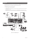
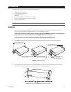
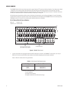
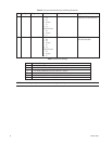
Figure 4. Installing Rack Ears
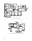
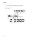
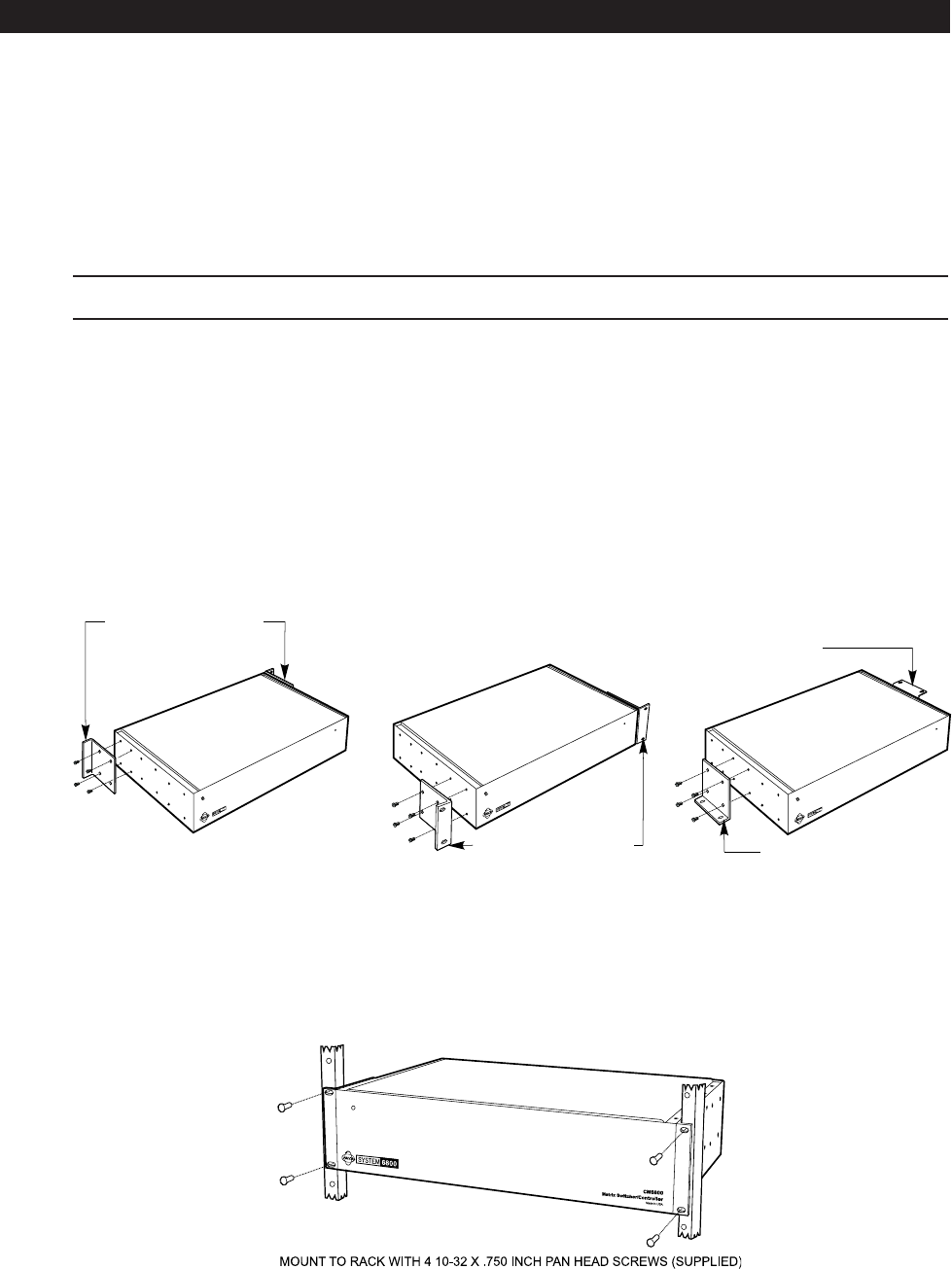
3. Use supplied pan head screws and washers to mount the CM6800E in a standard 19-inch (48.26 cm) equipment rack or wood or
sheet metal screws to mount against a flat surface, according to your installation requirements.
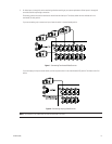
Figure 5. Mounting the CM6800E Matrix Switcher/Controller
POSITION BRACKETS FOR
RACK MOUNTING (FRONT)
POSITION BRACKETS FOR
FLUSH MOUNTING
(
WALL AND TABLE TOP
)
POSITION BRACKETS FOR
RACK MOUNTING (REAR)
NOTE: EACH CM6800 COMES
WITH 2 RACK EARS
POSITION BRACKETS FOR
UNDER-TABLE MOUNTING
INSTALLATION
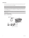
Unpack and inspect all parts carefully. The following parts are supplied:
1 CM6800E Switcher/Controller
4 10-32 x .750-inch pan head screws
4 .500” OD nylon washers
1 Power cord
4 6-foot (1.8 m) straight data cables with RJ-45 connectors
1 6-foot (1.8 m) reversed data cable with RJ-45 connectors
4 RJ-45 wall block terminals
NOTE: There are no user-serviceable parts inside this unit. Only authorized service personnel may open the unit.
MOUNTING
1. Select a suitable location for the CM6800E. It occupies 5.25 inches (13.34 cm) of vertical space, or three rack units (RUs), in a
universal mount. The CM6800E must be within 6 feet (1.8 m) of a suitable electrical outlet.
Follow proper installation practices and leave 1 RU above and below the CM6800E for ventilation. If installing a 96 x 16
system, in one vertical rack, leave 1 RU between each CM6800E-48X8 unit for ventilation.
Do not connect the power until the installation is complete. Refer to the
System Start-Up
section.
2. The CM6800E is shipped with the rack ears installed at the front. Reposition or remove ears as needed for your application.