Chapter 3 SCT 320 Operation 11
2.3.2 Terminal or RS-232 Port Settings
A terminal or RS-232 computer port must be set up as follows: 9600 baud, 8 data bits, no parity,
1 start bit, 1 stop bit.
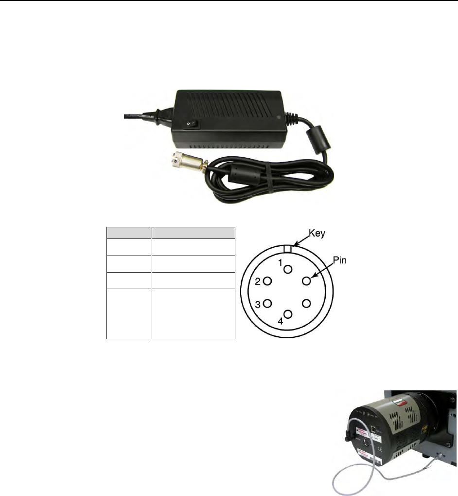
2.4 Power Supply with Input Cable
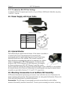
Figure 2-2. Power Supply
Pin#
Description
1
+5V
2
GND
3
GND
4
+24
Table 2-2. IsoPlane Power Connector Pin Arrangement
2.5 Internal Shutter
The IsoPlane has an optional internal shutter. If the shutter is installed, it
is located in the Turret Compartment and is mounted to the
spectrograph wall. Its shutter cable plugs into a keyed 2-pin shutter
connector in the floor of the IsoPlane. The external connector is
below the detector mounting plate and can be connected via a shutter
cable to a detector with a SHUTTER connector. If a detector does
not have a SHUTTER connector (PI-MAX detectors, for example),
the Princeton Instruments SHC-EXT Shutter Control Box can be
used to control the opening and closing of the internal shutter. If the control box is not available,
the internal shutter can be removed. Instructions for installing and removing the internal shutter
assembly are provided in Sections 2.13.1 and 2.13.2, respectively.
2.6 Mounting Accessories to an IsoPlane Slit Assembly
All Princeton Instruments spectroscopy accessories come with their own set of instructions for
proper mounting and operation. The instructions below are only general information. Please refer
to the individual instructions for detailed information.
Accessories: The full range of spectrograph accessories mount directly to the IsoPlane
entrance slit assembly (manual or motorized). To assist you in mounting accessories, a drawing


