22 IsoPlane
®
SCT 320 Manual Version 1.B
2.12 Slit Width Adjustments in the Model 718-1 Motorized 3mm Slit
The Model 718-1 motorized slit assembly is a self-calibrating, 10 µm to 3 mm
adjustable bilateral slit. Stepping-motor-controlled adjustments are made in 1 µm
increments over the full range. The Model 718-12 motorized slit assembly is a
self calibrating, 10 µm to 12mm adjustable bilateral slit. Stepping-motor
controlled adjustments are made in 5 µm increments over the full range.
Full control of the slit, including automated bandpass setting, is integrated
into LightField
®
and SpectraSense™ software. The slit motor is only
energized when you send the command via the software to control it. When
the power to a spectrograph is turned off, the slit remains in the position to
which it was last set. This position is stored in nonvolatile memory allowing slit position to be
maintained with power on or off.
2.13 Internal Shutter Installation/Removal
An IsoPlane may be ordered with an optional internal shutter at the entrance slit.
This shutter is controlled either by a detector via a shutter cable from the
detector’s Shutter connector to the Shutter connector on the IsoPlane or by an
Shutter Control box (Model SHC-EXT) available from Princeton Instruments.
2.13.1 Installing an Internal Shutter
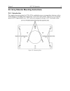
1. Using a 9/64” hex wrench, unscrew the four socket head screws that secure the Turret
Compartment cover to the top of the IsoPlane. Lift the cover and screws off of the
IsoPlane and set them aside.
2. Remove the grating turret. If you are not sure how to do this, refer to Section 2.14 Turret
Removal on page 24.
3. Use extreme care so as not to touch the grating surfaces.
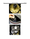
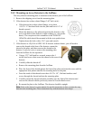
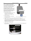
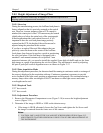
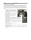
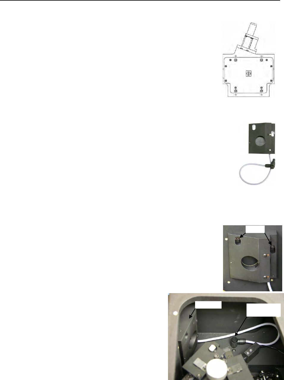
4. Mount the shutter assembly on the two socket head screws above
the entrance slit. You may need to back out the screws about five
turns.
5. Use the 9/64” hex wrench to tighten down the screws.
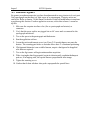
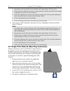
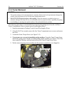
6. Connect the shutter cable to the connector in the floor of the
IsoPlane. Make sure the connector on the cable
aligns with the connector in the floor.
7. Re-install the grating turret. If you are not sure
how to do this, refer to Section 2.7 Turret
Installation on page 12.
8. Place the Turret Compartment cover on the
spectrograph. Replace and tighten all of the
cover screws.
Screws
Shutter
Shutter Cable
Connector


