Chapter 3 SCT 320 Operation 13
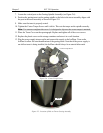
7. Locate the vertical post on the Grating Spindle Assembly (see Figure 2-6).
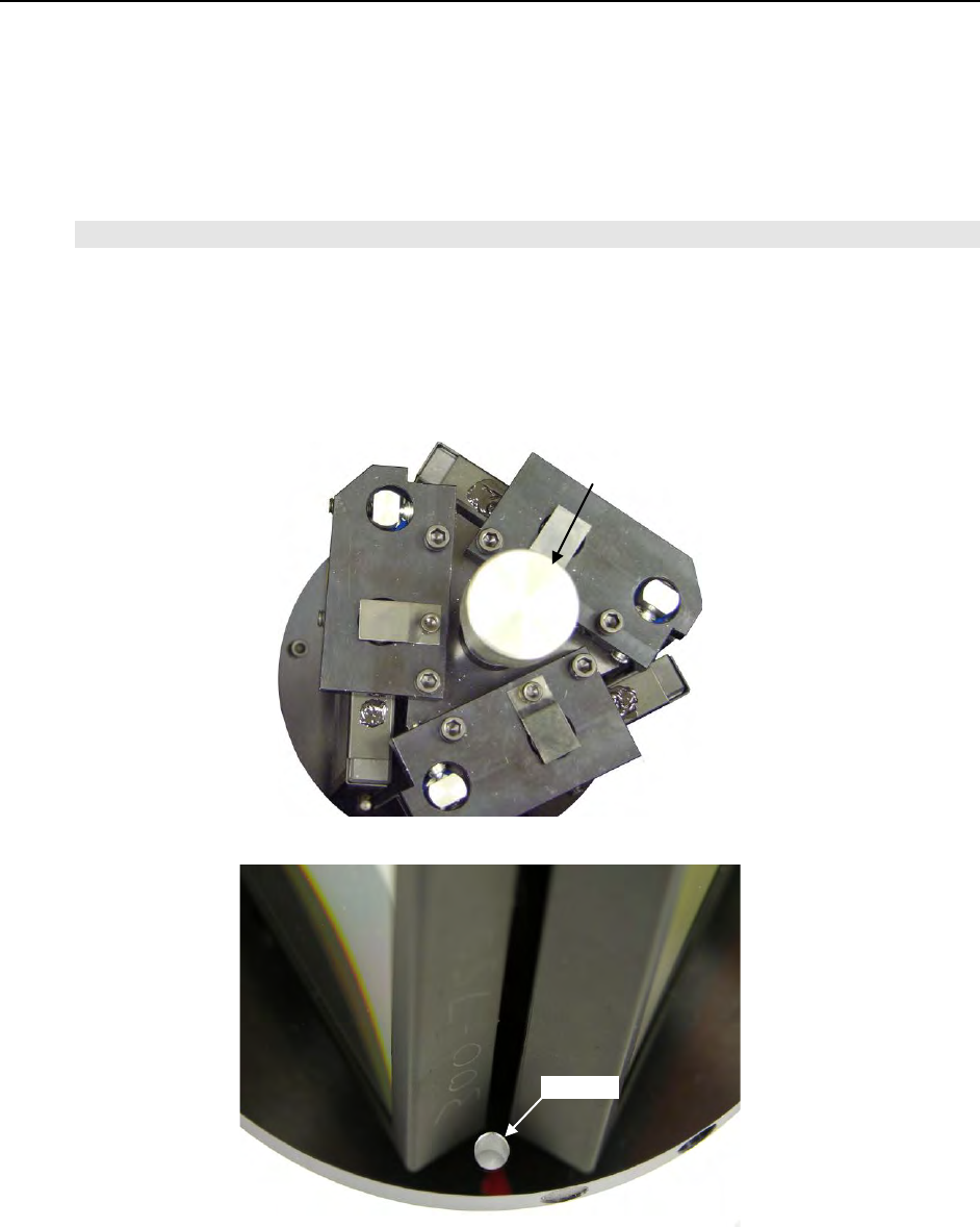
8. Position the grating turret on the grating spindle so the hole in the turret assembly aligns with
the post in the turret assembly as shown in Figure 2-8.
9. Make sure the turret is properly seated.
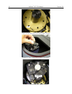
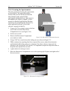
10. Tighten the Center Torque Screw until it clicks. This sets the torque on the spindle correctly.
Note: You cannot overtighten this screw. It is designed to slip once the correct torque is attained.
11. Place the Turret Cover on the spectrograph. Replace and tighten all of the cover screws.
12. Replace the plastic cover on the storage container and store it in a safe location.
13. Plug the power supply into an outlet and connect the supply to the IsoPlane. Turn on the
IsoPlane to allow for auto-identification of the grating turret. Note that if the power supply is
on while a turret is being installed, the IsoPlane should always be re-started afterwards.
Figure 2-4. Center Torque Screw
Figure 2-5. Location of Hole on Turret Grating Assembly
Hole
Center Torque Screw


