12 IsoPlane
®
SCT 320 Manual Version 1.B
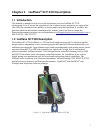
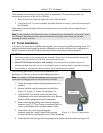
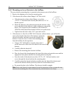
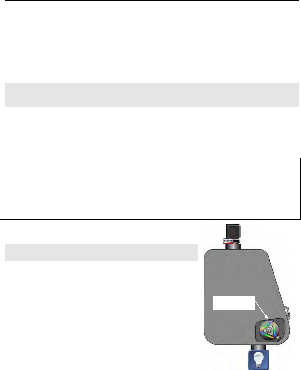
Turret
Compartment
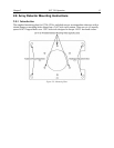
of the manual slit assembly has been provided in Appendix F. The general procedure for
mounting an accessory to the slit is as follows:
1. Place the accessory directly against the face of the slit body.
2. Using four (4) 8-32 screws normally provided with the accessory, secure the accessory to
the slit body.
Light sources fitted with light collection/focusing optics are normally factory-aligned to the
standard slit.
Note: In some instances with light sources, there is limited access to the bottom two screw holes. In this
case, Princeton Instruments provides special slotted holes in the light source housing to facilitate
mounting the source to the slit.
2.7 Turret Installation
If you have just received an IsoPlane spectrograph, you will need to install the grating turret. The
grating turret has been shipped in the same shipping box with the IsoPlane but is packaged in a
plastic container outside the IsoPlane housing to protect the gratings during shipment.
CAUTION
1. The optical surfaces in the spectrograph are extremely delicate and can be permanently damaged by
contact with solid objects as well as with most liquids and aerosols.
2. DO NOT TOUCH optical surfaces with anything. Wear thin protective powderless gloves to
minimize damage from body oils if you accidentally touch any optical surface, especially the grating.
3. Avoid talking or sneezing near optical surfaces. Do not breathe directly on them.
The following procedure is for the initial installation of a
grating turret. Observe proper optical handling procedures.
Note: See Section 2.15 Turret Interchange (starting on page 25) for
instructions on changing from one turret assembly to another.
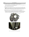
1. Locate the storage container with the grating turret to be
installed.
2. Become familiar with the components as labeled on
Figure 2-4, Figure 2-5, Figure 2-6 and Figure 2-8.
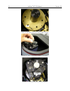
3. Using the 9/64” hex wrench, remove the four Turret
Compartment cover screws and remove the cover. Become
familiar with the grating turret and its components.
4. Before removing the grating turret from the shipping
container, use a 3/32” hex wrench to loosen the three set
screws on the bottom of the container (about 1 turn).
5. Then remove the cover from the shipping
container, grasp the Center Torque Screw and turn
it counter-clockwise until the turret can be lifted straight up.
6. Locate the hole near the edge between gratings on the grating turret assembly (see Figure 2-5).
Figure 2-3. Turret Compartment
Location


