20 IsoPlane
®
SCT 320 Manual Version 1.B
2. Adjustments to the Cap and Set Screws should be small, approximately 1/8
th
-turn or less.
3. If the Cap Screw is adjusted 1/8
th
-turn in a counter-clockwise direction, then the Set Screw should
be adjusted 1/8
th
-turn in a clockwise direction.
4. If the initial adjustment does not move the image far enough on the CCD, repeat the adjustments
to the Cap and Set Screws as stated in Notes a.2 and a.3 above.
5. Several small adjustments are recommended.
6. At the end of the procedure the Cap and Set Screws should be tight.
b. If the image is LOW, alternately loosen the Set Screw and tighten Cap Screw until the
image is centered.
Notes:
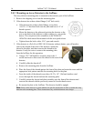
1. CAUTION: ONLY ADJUST THE SET AND CAP SCREWS AS INDICATED IN Figure 2-12.
ADJUSTMENTS TO OTHER SCREWS MAY RESULT IN SEVERE MISALIGNMENT OF
THE INSTRUMENT.
2. Adjustments to the Set and Cap Screws should be small, approximately 1/8
th
-turn or less.
3. If the Set Screw is adjusted 1/8th-turn in a counter-clockwise direction, then the Cap Screw
should be adjusted 1/8th-turn in a clockwise direction.
4. If the initial adjustment does not move the image far enough on the CCD, repeat the adjustments
to the Set and Cap Screws as stated in Notes b.2 and b.3 above.
5. Several small adjustments are recommended.
6. At the end of the procedure the Set and Cap Screws should be tight.
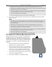
2.9 Single Point Detector Mounting Instructions
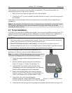
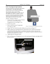
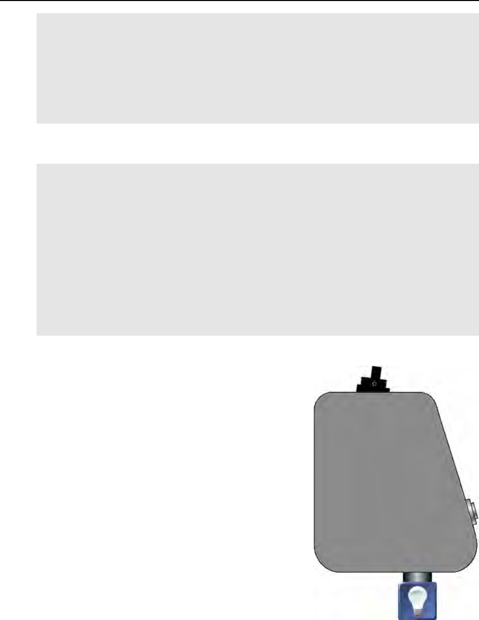
Single point detectors (such as the PD-438) mount directly to
the optional exit slit with mounting plate assembly of the
IsoPlane monochromator. Because the outcoming beam path
exits from the focusing mirror at 15 degrees to the housing, the
slit assembly is secured to a tapered mounting plate at the
exit port.
1. Position the detector so its labels are upright (the
optical axis is not vertically centered).
2. Mount the detector directly to the exit slit assembly
(already mounted to the tapered mounting plate at the
exit port) so its four mounting holes align correctly
with the tapped mounting holes of the slit assembly.
3. Insert the four 8-32 mounting screws and use a 9/64”
hex wrench to tighten the screws.
4. The detector should now be mounted correctly.


