


Manual for PlatiniX 2 series
Installation Instructions
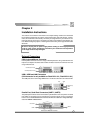
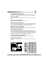
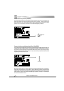
Line-in jack, Microphone-in jack, Speaker-out jack and MIDI/Joystick
Connector (available on PlatiniX 2-A/-AL, PlatiniX 2I-A/-AL)
The Line-in jack can be connected to devices such as a cassette or minidisc player to
playback or record. The Microphone-in jack can be connected to a microphone for voice input.
The Speaker-out jack allows you to connect speakers or headphones for audio output from
the internal amplifier.The MIDI/Joystick connector allows you to connect a game joystick or a
MIDI device.
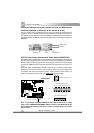
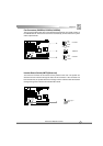
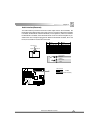
ATX12V Power Supply Connectors & Power Switch (POWER SW)
The PlatiniX 2 series of mainboards must use ATX12V power supply. Be sure to connect the
ATX 12V power supply plugs to the connectors in their proper orientation. The difference
between ATX12V power supply and ATX power supply is that ATX12V power supply
provides two additional power connectors: AUX power connector and +12V power con-
nector.
The power switch (POWER SW) should be connected to a momentary switch. When
powering up your system, first turn on the mechanical switch of the power supply (if one
is provided), then push once the power switch. When powering off the system, you
needn’t turn off the mechanical switch, just
Push once
*
the power switch.
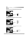
ATX Power Supply Connector
POWER
SW
1
GND
GND
12V 12V
GND 3.3V 3.3V GND GND 5V
1
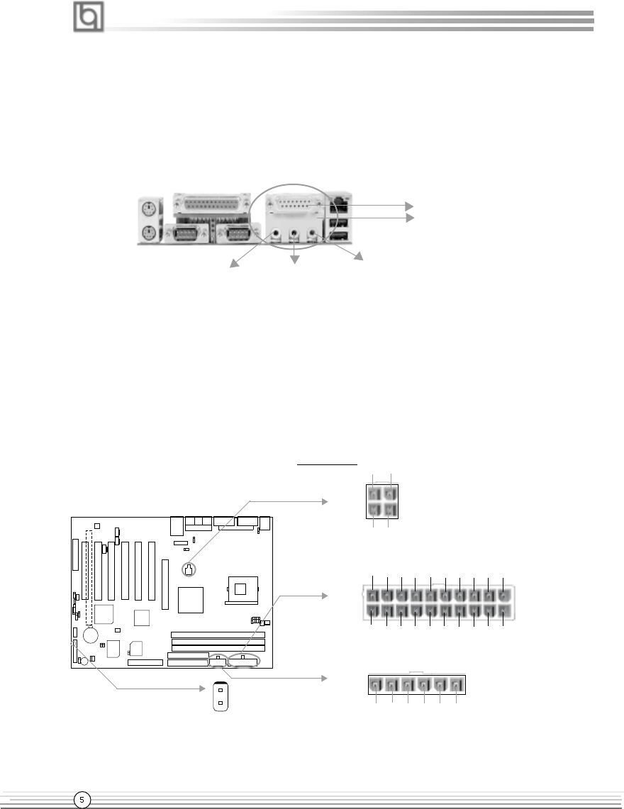
AUX Power Supply Connector
+12V Power Supply Connector
20
1
5V 5 V -5V
GND GND PS-ON -12V 3.3V
GND
12V 5VSB
5V GND
3.3V
GND
5V GND PW-OK 3.3V
GND
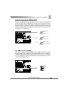
Note: * If you change “soft-off by PWR-BTTN” from default “Instant-off” to “Delay
4 Sec” in the “POWER MANAGEMENT SETUP” section of the CMOS SETUP, the
power button should be pressed for more than 4 seconds before the system
powers down.
MIDI/Joystick
Speaker out Line in Microphone in
Optional