


Rev.1.10 Jul 01, 2005 page 114 of 318
REJ09B0124-0110
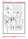
M16C/6N Group (M16C/6NK, M16C/6NM) 12. Timers
Under development
This document is under development and its contents are subject to change.
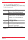
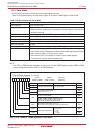
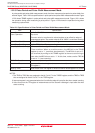
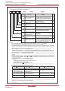
Item Specification
Count Source f1, f2, f8, f32, fC32
Count Operation • Up-count
• Counter value is transferred to reload register at an effective edge of
measurement pulse. The counter value is set to “0000h” to continue counting.
Count Start Condition Set the TBiS bit
(1)
to “1” (start counting)
Count Stop Condition Set the TBiS bit to “0” (stop counting)
Interrupt Request Generation Timing
• When an effective edge of measurement pulse is input
(2)
• Timer overflow. When an overflow occurs, the MR3 bit in the TBiMR
register is set to “1” (overflow) simultaneously. The MR3 bit is set to “0”
(no overflow) by writing to the TBiMR register at the next count timing or
later after the MR3 bit was set to “1”. At this time, make sure the TBiS bit
is set to “1” (start counting).
TBiIN Pin Function Measurement pulse input
Read from Timer Contents of the reload register (measurement result) can be read by reading
TBi register
(3)
Write to Timer Value written to the TBi register is written to neither reload register nor counter
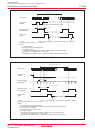
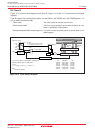
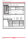
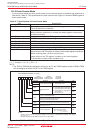
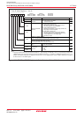
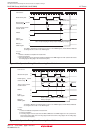
12.2.3 Pulse Period and Pulse Width Measurement Mode
In pulse period and pulse width measurement mode, the timer measures pulse period or pulse width of an
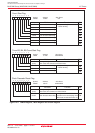
external signal. Table 12.8 lists specifications in pulse period and pulse width measurement mode. Figure
12.20 shows TBiMR register in pulse period and pulse width measurement mode. Figure 12.21 shows
the operation timing when measuring a pulse period. Figure 12.22 shows the operation timing when
measuring a pulse width.
Table 12.8 Specifications in Pulse Period and Pulse Width Measurement Mode
i = 0 to 5
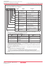
NOTES:
1.The TB0S to TB2S bits are assigned to the bit 5 to bit 7 in the TABSR register, and the TB3S to TB5S
bits are assigned to the bit 5 to bit 7 in the TBSR register.
2. Interrupt request is not generated when the first effective edge is input after the timer started counting.
3.Value read from the TBi register is indeterminate until the second valid edge is input after the timer
starts counting.