


Rev.1.10 Jul 01, 2005 page 237 of 318
REJ09B0124-0110
M16C/6N Group (M16C/6NK, M16C/6NM) 19. Programmable I/O Ports
Under development
This document is under development and its contents are subject to change.
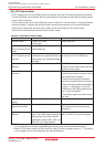
Table 19.2 Unassigned Pin Handling
Pin Name Connection
Ports P0 to P7, P8_0 to P8_4,
P8_6, P8_7, P9 to P14
(5)
XOUT
(4)
_______
NMI(P8_5)
AVCC
AVSS, VREF, BYTE
After setting for input mode, connect every pin to VSS via a resistor (pull-down);
or after setting for output mode, leave these pins open.
(1) (2) (3)
Open
Connect via resistor to VCC (pull-up)
Connect to VCC
Connect to VSS
NOTES:
1. When setting the port for output mode and leave it open, be aware that the port remains in input mode
until it is switched to output mode in a program after reset. For this reason, the voltage level on the pin
becomes indeterminate, causing the power supply current to increase while the port remains in input mode.
Furthermore, by considering a possibility that the contents of the direction registers could be changed
by noise or noise-induced runaway, it is recommended that the contents of the direction registers be
periodically reset in software, for the increased reliability of the program.
2.Make sure the unused pins are processed with the shortest possible wiring from the microcomputer
pins (within 2 cm).
3. When the ports P7_1 and P9_1 are set for output mode, make sure a low-level signal is output from the pins.
The ports P7_1 and P9_1 are N-channel open-drain outputs.
4. With external clock input to XIN pin.
5. The ports P11 to P14 are only in the 128-pin version. When not using all of the P11 to p14 pins may be
left open by setting the PU37 bit in the PUR3 register to “0” (P11 to P14 unusable), without causing any
problem.
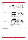
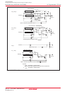
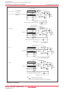
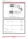
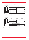
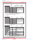
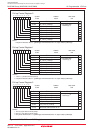
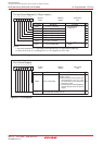
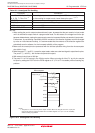
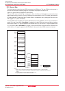
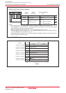
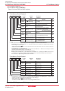
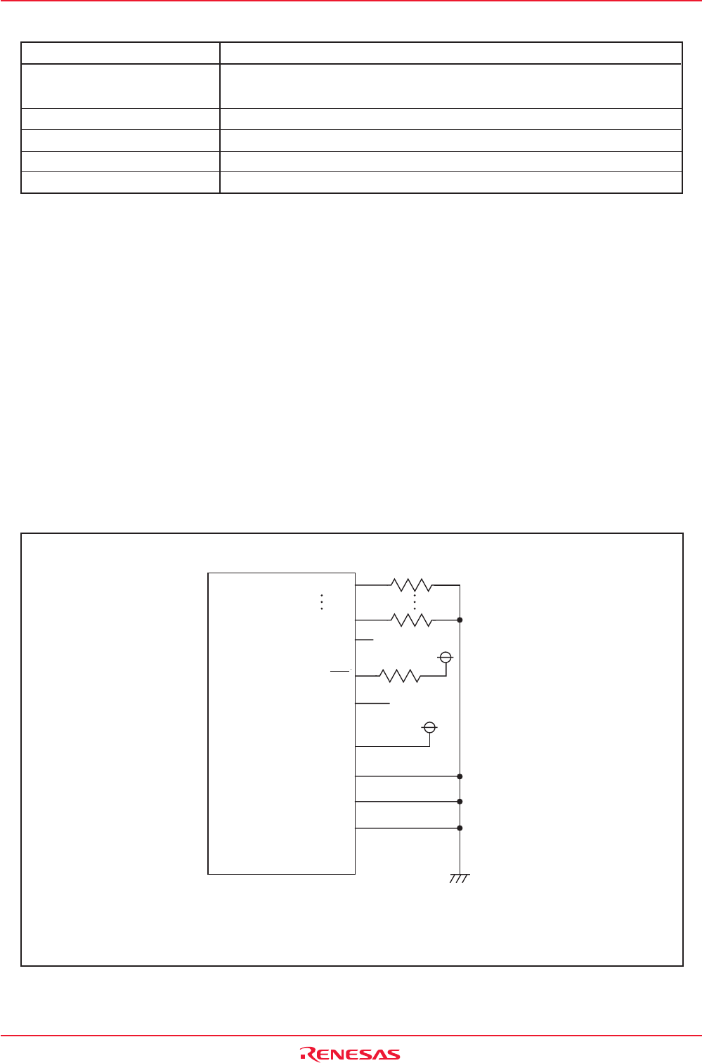
Figure 19.12 Unassigned Pins Handling
(Input mode)
(Input mode)
(Output mode)
Microcomputer
Port P0 to P14
(except for P8_5)
(1)
AVCC
BYTE
AVSS
VREF
XOUT
NMI
VCC
VCC
VSS
Open
Open
NOTE:
1.The ports P11 to P14 are only in the 128-pin version. When not using all of the P11 to p14 pins
may be left open by setting the PU37 bit in the PUR3 register to "0" (P11 to P14 unusable),
without causing any problem.