


Rev.1.10 Jul 01, 2005 page 200 of 318
REJ09B0124-0110
M16C/6N Group (M16C/6NK, M16C/6NM) 17. CRC Calculation
Under development
This document is under development and its contents are subject to change.
17. CRC Calculation
The Cyclic Redundancy Check (CRC) operation detects an error in data blocks. The microcomputer uses a
generator polynomial of CRC-CCITT (X
16
+ X
12
+ X
5
+ 1) to generate CRC code.
The CRC code consists of 16 bits which are generated for each data block in given length, separated in 8-bit
unit. After the initial value is set in the CRCD register, the CRC code is set in that register each time one byte
of data is written to the CRCIN register. CRC code generation for one-byte data is finished in two cycles.
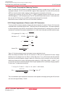
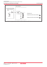
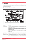
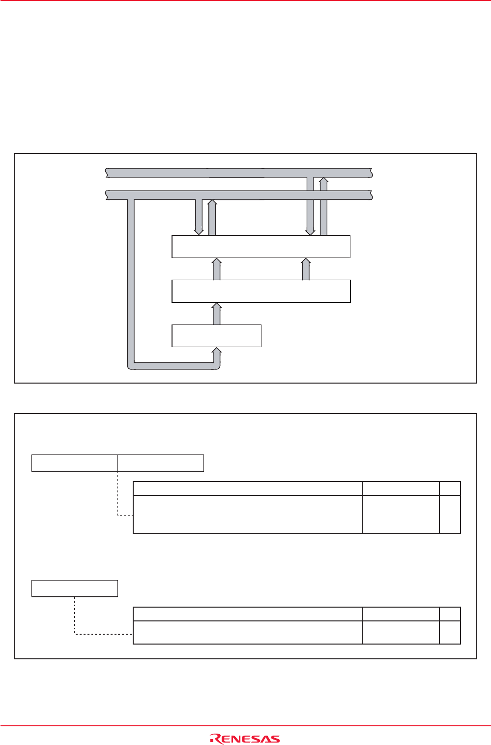
Figure 17.1 shows the block diagram of the CRC circuit. Figure 17.2 shows the CRC-related registers.
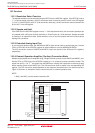
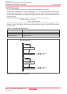
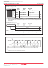
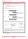
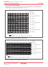
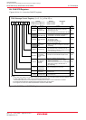
Figure 17.3 shows the calculation example using the CRC operation.
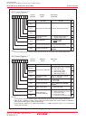
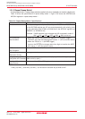
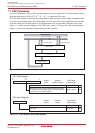
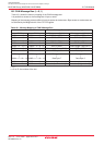
Figure 17.2 CRCD Register and CRCIN Register
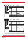
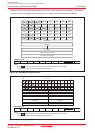
Figure 17.1 CRC Circuit Block Diagram
When data is written to the CRCIN register after setting
the initial value in the CRCD register, the CRC code can
be read out from the CRCD register.
0000h to FFFFh
Function Setting Range
RW
RW
CRCD
Symbol After Reset
Indeterminate
03BDh to 03BCh
Address
b7 b0b7 b0
(b15) (b8)
CRC Data Register
Data input
00h to FFh
Function Setting Range
RW
RW
CRCIN
Symbol After Reset
Indeterminate
03BEh
Address
b7 b0
CRC Input Register
High-order 8 bitsLow-order 8 bits
CRCIN register
x
16
+x
12
+x
5
+1
Data bus high-order
Data bus low-order
CRCD register
CRC code generating circuit