


( 18 / 84 )
IMPORTANT
Note on Differences Between the Actual MCU and Emulator:
• Operation of the emulator differs from that of the actual MCU as listed below.
(1) Reset condition
Set the time for starting up (0.2 Vcc to 0.8 Vcc) 1 µs or less.
(2) Initial values of MCU's internal resources at power-on
(3) Internal memories (ROM and RAM) capacities etc.
With this emulator system, regardless of ROM and RAM of the MCU you use, all the areas
other than the SFR area can be read and written into.
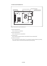
(4) Characteristics of ports P0 to P5
Ports P0 to P5 are connected via emulation circuits. The device used for the port emulation
circuit is the IC21 (ALTERA EPF6016QC208-2).
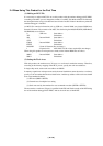
(5) Oscillator circuit
• Make note that in the oscillator circuit where a resonator is connected between pins XIN and
XOUT, oscillation does not occur because a flexible cable, buffer IC and other devices are used
between the evaluation MCU and the target system. It is same for sub-clock oscillators (XCIN
and XCOUT).
• For notes on when using the oscillator circuit on the target system, refer to "3.3 (2) Using
the Oscillator Circuit on the Target System" (page 31).
(6) A-D conversion function
As a flexible cable and other devices are used between the evaluation MCU and the target
system, some characteristics are slightly different from those of the actual MCU.
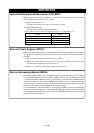
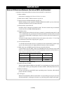
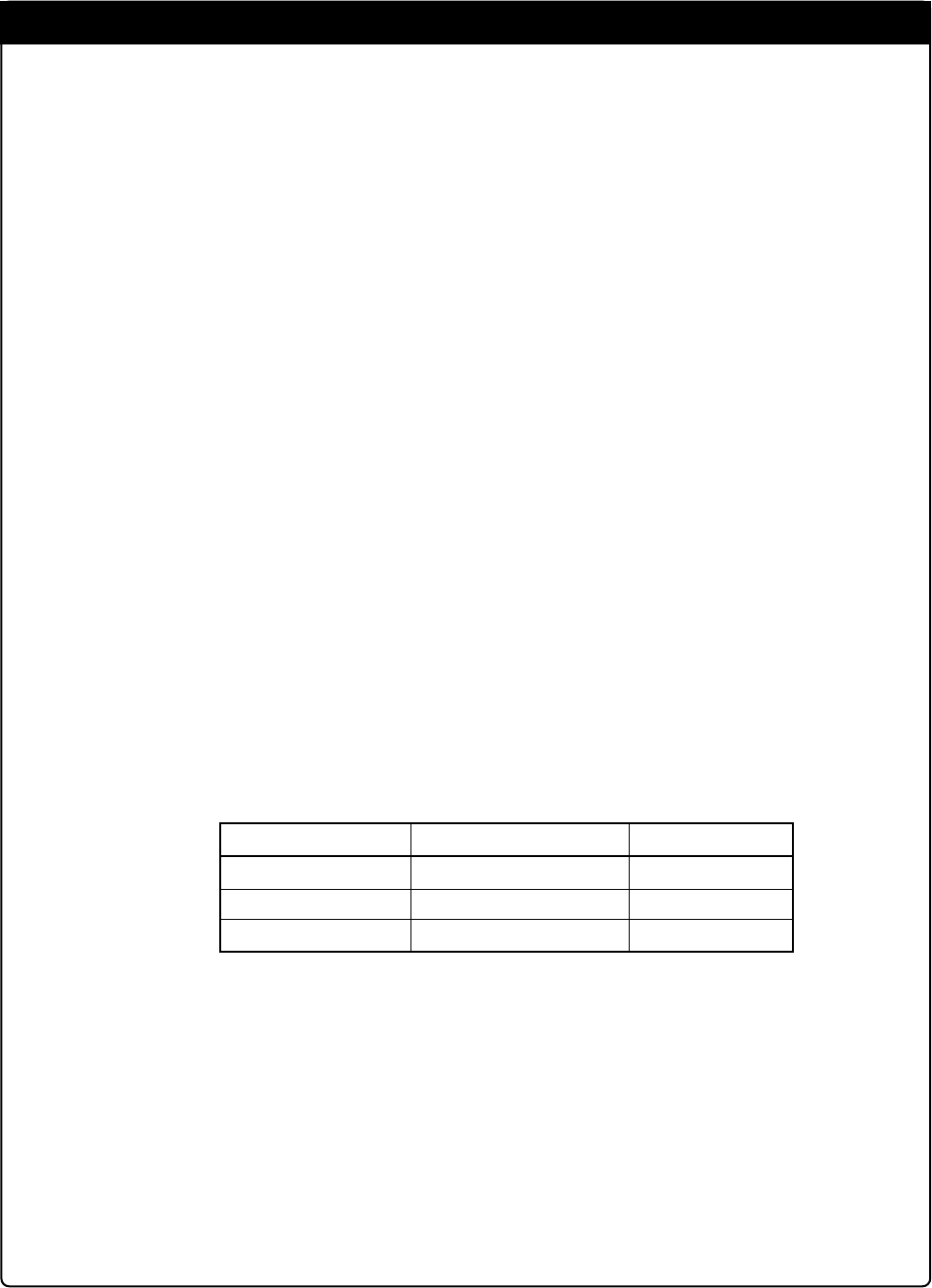
(7) DBC, single-step and BRK instruction interrupt vector table addresses
As the emulator uses the DBC, single-step and BRK instruction interrupt vector table
addresses, when reading these addresses, the downloaded data cannot be read (see Table 1.2).
Table 1.2 Vector table addresses for the emulator
*1 Interruption for the emulator only
(8) Address and status of BHE*
When the internal RAM or ROM area of the MCU is accessed during user program execution,
the actual MCU retains a preceding address and status of BHE*, while this product does not.
(9) Status of a data bus
In stop or wait mode, the actual MCU retains a preceding status of a data bus, while with this
product a data bus is floating.
(10) ALE signal
When the internal RAM or SFR area of the MCU is accessed during user program execution,
with the actual MCU, ALE output is fixed to Low, while this product outputs ALE signal.
Factor of interruption
DBC*
1
Single-step*
1
BRK instruction
Vector table addresses
FFFF4h--FFFF7h
FFFECh--FFFEFh
FFFE4h--FFFE7h
Data read
Indefinite
Indefinite
Indefinite